Lattice structural elements
Lattice structural elements
Lattice2d element
Represents two-node lattice element. Each node has 3 degrees of freedom. The element is based on the Rigid Body Spring Model originally developed by Kawai and later delveloped by Bolander for modelling fracture in concrete. The main idea is to model the elastic and inelastic response of a connection of two nodes by a set of springs located at the contact facet of two rigid bodies, which is the mid-cross-section of the element. Displacement jumps are computed at the mid-cross-section, which are smeared out over the element length in the form of strains. The element is defined in x,y plane (see Figure Lattice2d element. Node numbering, DOF numbering and definition of integration point C.). The element features are summarized in Table Table 71.
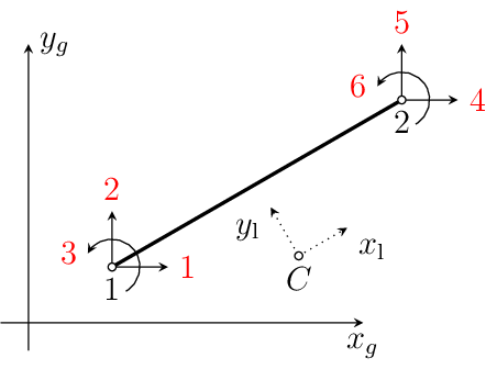
Fig. 32 Lattice2d element. Node numbering, DOF numbering and definition of integration point \(C\).
Keyword |
lattice2d |
Description |
2d lattice element |
Specific parameters |
|
Parameters |
|
Unknowns |
Three dofs (\(u\)-displacement, \(v\)-displacement, \(w\)-rotation) are required in each node. |
Tests/Examples |
lm/lattice2drandom.in, lm/latticeplastdamvisco_mps_1.in, lm/latticeplastdamvisco_mps_2.in, lm/latticeplastdamvisco_mps_3.in, lm/latticedamagevisco_mps_1.in, lm/latticeplastdamvisco3drandom.in, lm/latticeviscoelastic_mps_1.in, lm/lattice2 dframecircle.in, lm/lattice2dframesteelplastic.in |
The theory of lattice2d is described in [GraJir10]
Used with a circular LatticeCS (shape 1, radius), lattice2d acts as
a Timoshenko frame element in the \(x\)-\(y\) plane. The area
\(A = \pi r^2\), the second moment of area \(I = \pi r^4/4\) and the shear
area \(0.9 A\) are computed from the radius, and each can be overridden by
area, iz and shearareay of the cross section. Together with
the frame materials latticeframeelastic and latticeframesteelplastic, this
allows modelling, for example, yielding reinforcement bars in 2d. The generalised
strains are the axial strain, the shear strain and the curvature at point \(C\),
and the corresponding generalised stresses are the normal force \(N\), the shear
force \(V\) and the bending moment \(M_z\). The element has a single
integration point, so the bending moment is constant within each element and
several elements per member are needed where yielding is expected.
LatticeBoundary2D element
Represents three-node lattice element for boundary of 2d periodic cells. The first two
nodes have 3 degrees of freedom as for the element lattice2d. The third node is used to
control the loading of the periodic cell. It has three components which are
displacements, which are produces of the macroscopic (average) strain components and
length of the peridodic cell as \(aE_{xx}\), \(bE_{xx}\) and \(bG_{xy}\) and
the length of the periodic cell. The DOFs of the node that lies outside the periodic are
computed from those of the periodic image inside the cell and the DOFs at the third node
(Fig. 33). The coordinates \(x\) and \(y\) of the
third node are the lengths \(a\) and \(b\) of the periodic cell, respectively.
The element is defined in x,y plane. The strain components at the additional node have
the meaning of average strains in the periodic cell. The specific input parameters for
this element in addition to those used for lattice2d are shown in Table
lattice2dboundarysummary.
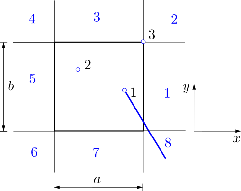
Fig. 33 latticeboundary2D element. Elements with cross boundary of periodic cell use DOFs of node inside cell and average strain values of periodic cell.
Keyword |
latticeboundary2D |
Description |
2d lattice boundary element |
Specific parameters |
|
Parameters |
|
Unknowns |
Nine DOFs are required, which are \(u\)-displacement, \(v\)-displacement and \(w\)-rotation at nodes 1 and 2, and \(aE_{xx}\), \(bE_{yy}\) and \(bG_{xy}\) at node 3. |
Reference |
|
Tests/Examples |
Lattice3d element
Lattice3d represents a two-node 3d lattice element. Each node has six degrees of freedom as shown in Fig. 34. The element is based on the Rigid Body Spring Model originally developed by Kawai and later delveloped by Bolander for modelling fracture in concrete. The main idea is to model the elastic and inelastic response of a connection of two nodes by a set of springs located at the contact facet of two rigid bodies, which is the mid-cross-section of the element. The properties of the mid-cross-section are internally computed from its vertices which are given as input in the global coordinate sytem. Displacement jumps are computed at the mid-cross-section, which are smeared out over the element length in the form of strains. The input parameters for this element are shown in Table 73.
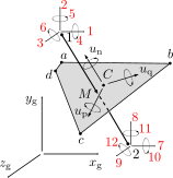
Fig. 34 Lattice3d element. Node numbering, DOF numbering, cross-section vertices and local coordinate system at integration point \(C\).
Keyword |
lattice3d |
Description |
3d lattice element |
Specific parameters |
|
Parameters |
|
Unknowns |
Six dofs (\(u\)-displacement, \(v\)-displacement, \(w\)-displacement, \(u\)-rotation, \(v\)-rotation and \(w\)-rotation) are required in each node. |
Reference |
|
Tests/Examples |
lm/lattice3dshell.in, lm/lattice3dshell_lle.in, lm/lattice3dshell_lle_twist_n4.in, lm/lattice3d3.in, lm/lattice3d4.in, lm/lattice3drandom.in, lm/lattice3ddamplast3.in, lm/lattice3dshell_dmg_bend_n7.in, lm/lattice3dbondplast1.in, lm/lattice3delastic.in (and 17 more) |
Lattice3dBoundary element
This element represents a three-noded 3d lattice element for boundaries of 3d periodic cells. The first two nodes have 6 degrees of freedom as for the element lattice3d. The third node is used to control the loading of the periodic cell using three normal (\(aE_{xx}\), \(bE_{yy}\) and \(zE_{zz}\)) and three shear strain (\(cG_{yz}\), \(cG_{xz}\), \(bG_{xy}\)) components. Here, \(a\), \(b\) and \(c\) are the three dimensions of the periodic cell. The DOFs of the node that lies outside the periodic are computed from those of the periodic image inside the cell and the DOFs at the third node (Fig. 35). The connection between periodic nodes is defined as
Here, \(\mathbf{x}^{'}\) and \(\mathbf{x}\) are the nodes inside and outside, respectively, and \(\mathbf{M}\) is the translation matrix, for which the input is provided in the form of a location parameter as shown in Table Table 74.
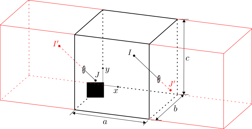
Fig. 35 Lattice3dboundary element. Elements with cross boundary of periodic cell use DOFs of node inside cell and average strain values of periodic cell.
Keyword |
lattice3dboundary |
Description |
3d lattice boundary element |
Specific parameters |
|
Parameters |
|
Unknowns |
Six dofs (\(u\)-displacement, \(v\)-displacement, \(w\)-displacement, \(u\)-rotation, \(v\)-rotation and \(w\)-rotation) are required in each of the first two node. Node 3 requires the 6 quantities to control the periodic cell \(aE_{xx}\), \(bE_{yy}\), \(zE_{zz}\), \(cG_{yz}\), \(cG_{xz}\) and \(bG_{xy}\) |
Reference |
|
Tests/Examples |
LatticeLink2d element
This element is the 2d counterpart of latticelink3d. It is a two-node link in the
\(x\)-\(y\) plane with three degrees of freedom per node (\(u\), \(v\) and
the rotation about \(z\)), for example between a frame node (lattice2d) and a node
embedded in a 2d continuum. The jump of the second node relative to the first, including
a rigid arm from the first node to the second, is expressed in a local system with the
first axis along dirvector: slip along the bar, lateral jump across it and
relative rotation. The material is evaluated in 2d lattice mode, i.e. as the components
1, 2 and 6 of the 3d lattice material, so the same bond materials (e.g. latticeslip,
with a1 scaling the lateral and a2 the rotational stiffness) can be used
in 2d and 3d. The bond area is \(\pi\) diameter length. The input
parameters are shown in Table 75.
Keyword |
latticelink2d |
Description |
2d lattice link element |
Specific parameters |
|
Parameters |
|
Unknowns |
Three dofs (\(u\)-displacement, \(v\)-displacement and \(w\)-rotation) are required in each node. |
Tests/Examples |
LatticeLink3d element
This element represents a two-node 3d link element connecting 3d beam and 3d lattice elements. Each node has six degrees of freedom. The node ordering is important: the first node carries the rigid arm and must therefore have rotational degrees of freedom, while the slip (displacement jump) is evaluated at the second node. Which physical entity is placed first is the user’s modelling choice; it only has to be the node from which the rigid arm is offset. For a lattice model both matrix and reinforcement nodes usually have rotational degrees of freedom, so the matrix node is typically given first and the reinforcement node second, evaluating the slip at the reinforcement. The input parameters for this element are shown in Table 76.
Keyword |
latticelink3d |
Description |
3d lattice link element |
Specific parameters |
|
Parameters |
|
Unknowns |
Six dofs (\(u\)-displacement, \(v\)-displacement, \(w\)-displacement, \(u\)-rotation, \(v\)-rotation and \(w\)-rotation) are required in each node. |
Reference |
|
Tests/Examples |
Latticelink3dboundary
Represents three-node 3d boundary link element connecting 3d beam and 3d lattice elements. The first two nodes have the same meaning as for latticelink3d. The third node is used to control the loading of the periodic cell using three normal (xx, yy and zz) and three shear strain (yz, xz, xy) components. The specific input parameters for this element in addition of those for latticelink3d are shown in Table Table 77.
Keyword |
latticelink3dboundary |
Description |
3d lattice link boundary element |
Specific parameters |
|
Parameters |
|
Unknowns |
Six dofs (\(u\)-displacement, \(v\)-displacement, \(w\)-displacement, \(u\)-rotation, \(v\)-rotation and \(w\)-rotation) are required in each node. |
Reference |
Lattice3dNl element
Lattice3dNl is the geometrically nonlinear (large-rotation) counterpart of the lattice3d
element. It accepts the same input and the same cross-section options (facet/shell via
polycoords, or beam via the cross-section properties together with
zaxis and s), but the displacement jumps and nodal forces are
evaluated in the deformed configuration, so the element is suitable for large rotations
and catenary action. The rotational part of the generalised strain is the exact relative
rotation of the two nodes, i.e. the axial vector of \(\mathbf{R}_2
\mathbf{R}_1^{\mathrm{T}}\), which reduces to the difference of the nodal rotation
vectors for rotation about a single axis.
Keyword |
lattice3dnl |
Description |
3d geometrically nonlinear lattice element |
Specific parameters |
|
Parameters |
|
Cross-section |
As for the lattice3d element. |
Unknowns |
Six dofs (\(u\)-displacement, \(v\)-displacement, \(w\)-displacement, \(u\)-rotation, \(v\)-rotation and \(w\)-rotation) are required in each node. |
Reference |
|
Tests/Examples |
lm/lattice3dnlshell.in, lm/lattice3dnl_logrot.in, lm/lattice3dnlshell_dmg_bend_n7.in, lm/latticelink3dnl_assembly.in, lm/latticeframe3dnl.in |
LatticeContact3d element
LatticeContact3d is a two-node contact (interface) element. In contrast to lattice3d it
couples only the translational degrees of freedom of the two nodes, so it can connect
6-DOF lattice nodes as well as 3-DOF continuum nodes, and it transmits no moment. The
translational displacement jump between the nodes is expressed in a local frame (one
normal and two shear directions) and passed to the material as a three-component
generalised strain. The jump is not divided by the element length, so the material
works directly with displacement jumps. Internal forces and stiffness are scaled by the
contact area. A typical use is the bond between reinforcement and concrete: the
converter emits latticecontact3d for all elements of a given material with
#@element material <mat> latticecontact3d, using the Voronoi facet as
polycoords. The element is summarised in Table 79.
Keyword |
latticecontact3d |
Description |
3d node-to-node lattice contact (interface) element |
Specific parameters |
[ |
Parameters |
|
Cross-section |
A latticecs record, as for the lattice3d element. |
Material |
A lattice material acting on the three translational components, typically latticebondplast; the rotational components 4 to 6 remain zero. |
Unknowns |
Three dofs (\(u\)-displacement, \(v\)-displacement, \(w\)-displacement) are required in each node. Rotational dofs present at the nodes are not coupled. |
Tests/Examples |
lm/contact_single.in, lm/contact_cubes_separation.in, lm/contact_cubes_shear.in |