Dof manager records
These records describe the individual dof managers: nodes, or element sides if they manage any DOFs.
Record syntax
DofManagerType num (in)
[load (ia)] [DofIDMask (ia)]
[bc (ia)] [ic (ia)]
[doftype (ia)] [masterMask (ia)]
[boundary]
<[globnum (in)]>
<[shared] | [remote] |
[null]>
<[partitions (ia)]>
The order of the records is arbitrary and the dof manager number is given by
num. Numbering may be non-contiguous: think of the number as a label
assigned to an individual dof manager, by which it is referenced.
Degrees of freedom
By default the nodal DOFs are determined by asking all the connected elements.
Additional DOFs can be requested with the DofIDMask array, which also
fixes their physical interpretation.
- [
DofIDMask(ia)] Each item describes the physical meaning of the corresponding DOF in the dof manager, using the
DofIDItemvalues in the table below.
Important
Two DOFs with the same physical meaning may not appear in the same dof manager.
Value |
Name |
Meaning |
|---|---|---|
1, 2, 3 |
|
Displacement along the x, y, z axis |
4, 5, 6 |
|
Rotation about the x, y, z axis (right-hand rule) |
7, 8, 9 |
|
Velocity along the x, y, z axis |
10 |
|
Temperature field |
11 |
|
Pressure field |
12, 13 |
|
DOFs of gradient-type constitutive formulations |
14 |
|
Mass concentration of the first constituent |
15, 16, 17 |
|
Components of the change in the director field |
18 |
|
Inhomogeneous thickness strain along the director field |
19–22 |
|
Constant and linear parts of the boundary displacement, used by the Trefftz element |
23, 24 |
|
Relative twist times the deplanation function, and the relative twist,
used by the |
25, 26, 27 |
|
Lagrange multipliers in the x, y, z direction |
28, 29, 30 |
|
Independent traction field in the x, y, z direction |
31–39 |
|
Macroscopic strain components |
40, 41, 42 |
|
Macroscopic shear strain components |
43–50 |
|
Macroscopic curvature components |
51, 52, 53 |
|
Macroscopic reinforcement slip field |
54 |
|
Volume fraction |
55 |
|
Pressure field of the second phase |
56 |
|
Mass concentration of the second constituent |
The authoritative list is the DofIDItem enumeration in
src/core/dofiditem.h.
Note
XFEM enrichment DOFs are not in this range. They are allocated
dynamically by the enrichment items, starting above MaxDofID (500), so
they are never written in a DofIDMask.
Boundary and initial conditions
Primary (Dirichlet) boundary conditions are applied through bc,
natural boundary conditions through load.
- [
bc(ia)] Primary boundary conditions. The size must equal the number of DOFs in the dof manager, and the i-th value relates to the i-th DOF; the ordering and physical meaning of the DOFs follow from the domain record, and may be set per dof manager with
DofIDMask. The values are boundary condition record numbers, or zero where no primary condition applies to that DOF. A compatible type is required: primary conditions needBoundaryConditionrecords. When omitted, no primary condition is applied.- [
load(ia)] Record numbers of the natural boundary conditions that are applied; the required record type is
NodalLoad. Where more than one natural condition applies, the actual value is the sum of all contributions. Note that the values of a natural condition for the individual DOFs are given in its own record, not here. When omitted, no natural condition is applied.- [
ic(ia)] Initial conditions, in the same layout as
bc. The size should equal the number of DOFs in the dof manager, and the values are initial condition record numbers, or zero where no initial condition applies — in which case a zero initial value is assumed.- [
boundary] A flag marking the dof manager as lying on the boundary of the domain.
Master-slave DOFs
doftype and masterMask connect some of a dof manager’s DOFs —
the slave DOFs — to the corresponding DOF, by physical meaning, of another dof
manager — the master DOF. The master-slave principle makes it easy to model,
for example, a structural hinge, where several elements are connected by
introducing several nodes with the same coordinates that share the same
displacement DOFs while each keeps its own rotational DOFs.
- [
doftype(ia)] Type of each DOF to create:
0a master DOF,1a simple slave DOF linked to a single master DOF,2a general slave DOF that may depend on different DOFs belonging to different dof managers. When omitted, all DOFs are created as master DOFs.- [
masterMask(ia)] Required whenever
doftypeis given. Its meaning depends on the type of the dof manager and is described in the sections below.
Parallel mode
Note
This section applies only to the parallel build. See The parallel model for the overall picture.
Exactly one of shared, remote and null may be used
for a given dof manager. If none is used, the dof manager is a local one for
the partition.
- [
shared] The dof manager is shared by neighbouring partitions, and the contributions from all contributing domains are summed. Typical of the node-cut algorithm; see Fig. 2 and Fig. 3.
- [
remote] The dof manager in the active domain is only a mirror of a remote dof manager, so the remote values have to be copied into the local ones. Typical of the element cut; see Fig. 5.
- [
null] A so-called null dof manager, which should be shared only by remote elements. Remote elements exist only so that a nonlocal constitutive model can average efficiently, transferring just the local material values to be averaged. Null nodes therefore serve only to compute the real integration point coordinates of remote elements; there is no reason to maintain their unknowns, so they are assigned no equation number and contribute nothing to the governing equations of the local partition. See Fig. 3.
- [
partitions(ia)] For a shared dof manager, the list of remote partitions sharing it; for a remote one, the partition holding its remote counterpart. The local partition must not be included in the list.
- [
globnum(in)] Global number of the dof manager, unique across all partitions. The parallel version requires a unique global numbering of dof managers to link the partitions together.
Slave DOFs are allowed, but their masters have to be in the same partition. The masters may themselves be remote copies.
Partitioning strategies
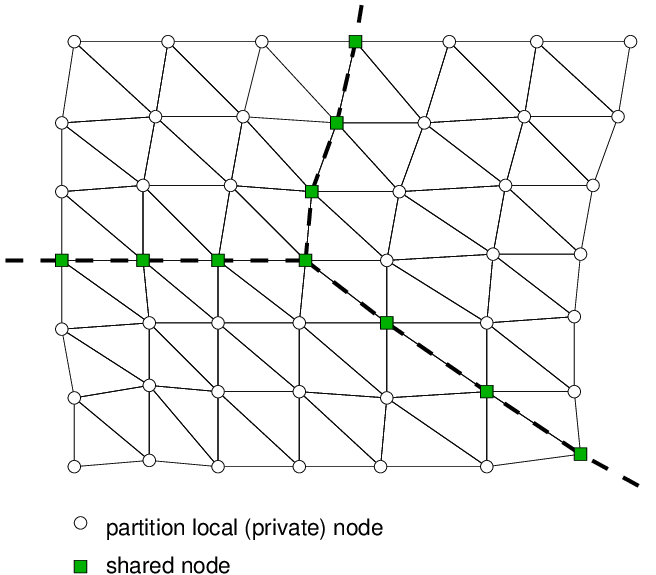
Fig. 1 Node-cut partitioning.
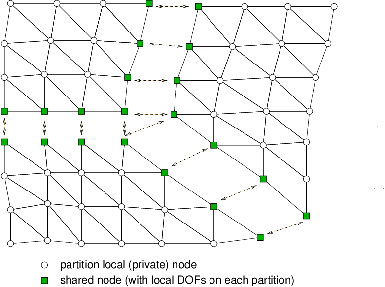
Fig. 2 Node-cut partitioning, local constitutive mode.
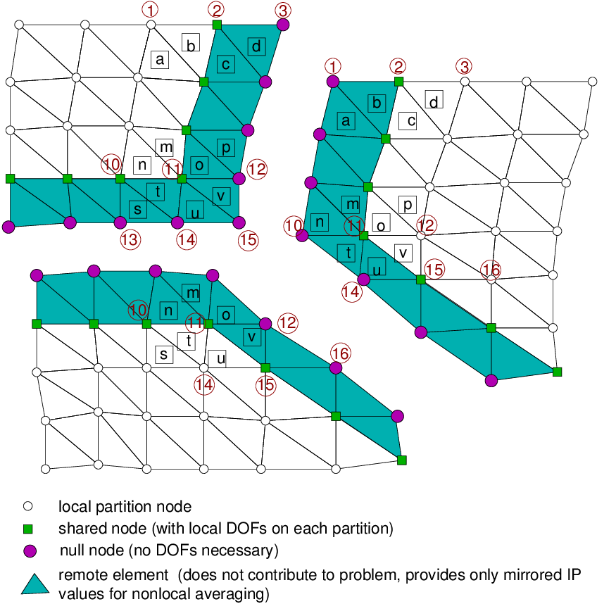
Fig. 3 Node-cut partitioning, nonlocal constitutive mode.
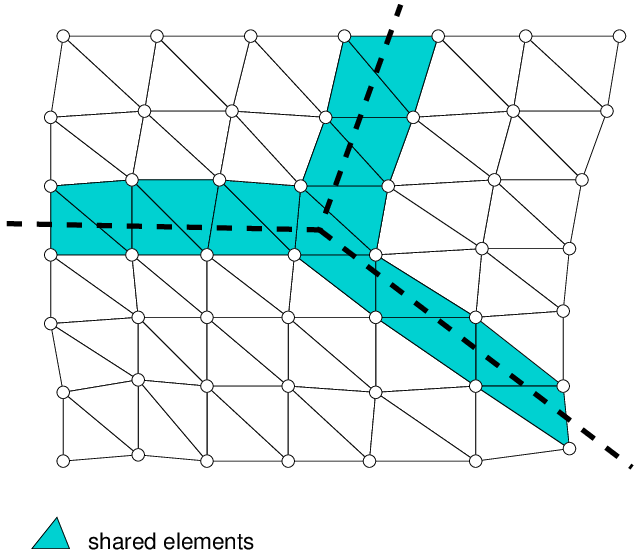
Fig. 4 Element-cut partitioning.
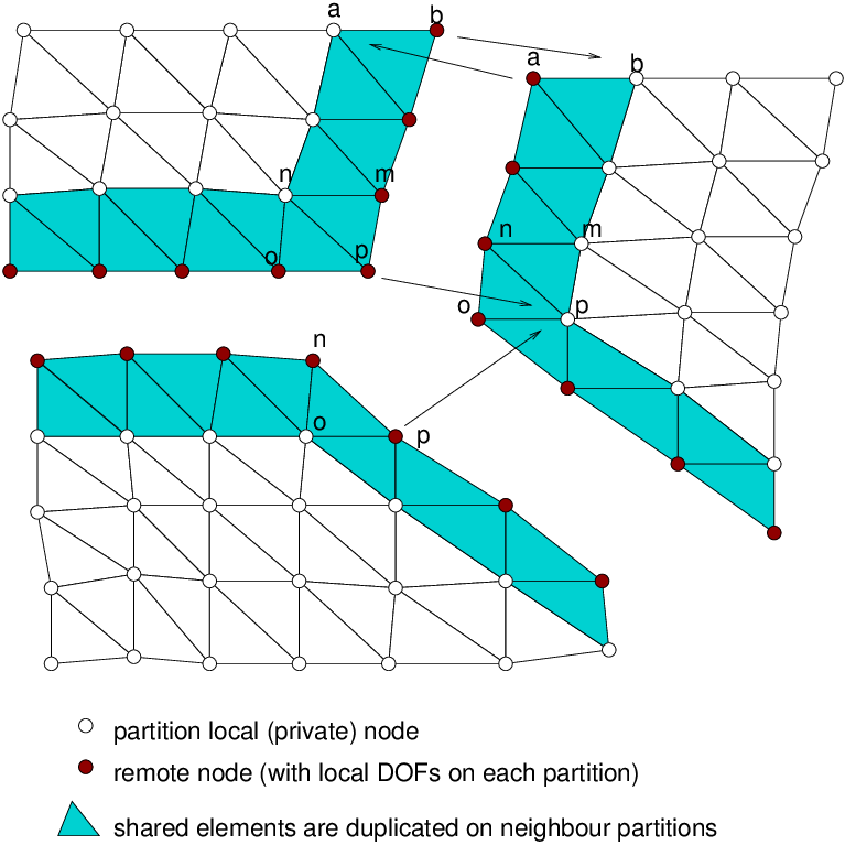
Fig. 5 Element-cut partitioning, local constitutive mode.
Supported dof manager types
Node
An abstraction for a finite element node.
Record syntax
Node num (in) coords (ra)
[lcs (ra)]
Parameters
coords(ra)Coordinates of the node in the global coordinate system: the x, y and, depending on the problem, z coordinate.
- [
lcs(ra)] A user-defined local coordinate system in the node. The array holds six numbers: the first three are a direction vector of the local x-axis, the next three a direction vector of the local y-axis, and the local z-axis follows from the vector product. A right-handed system is assumed. When a local system is given, the boundary conditions and the applied loading are specified in it, and the reactions and displacements are also reported in it. By default the coordinate system in a node is the global one.
Master-slave support
A node can create only master and simple slave DOFs, so the permitted values of
doftype are 0 and 1. For a node, masterMask is an
array whose size equals the number of DOFs, the i-th value giving the master
dof manager to which the i-th DOF is directly linked; DOFs with the same
physical meaning are linked together. A local coordinate system in a node with
linked DOFs is supported, but it must be exactly the same as on the master.
Rigid arm node
A node connected to another node — the master — by a rigid arm. Its DOFs may be linked to the master through the rigid arm transformation, or be independent.
The rigid arm node avoids the very stiff elements otherwise used to model a rigid-arm connection: it maps its DOFs onto the master DOFs by simple transformations, assuming small rotations, so contributions to the rigid arm node can be localised directly into the master’s equations. A rigid arm node can be loaded independently of its master, but cannot have boundary or initial conditions of its own — these follow entirely from the master’s conditions.
Record syntax
RigidArmNode num (in) coords (ra)
master (in) [masterMask (ia)]
[lcs (ra)]
Parameters
coords(ra)Coordinates of the node in the global coordinate system.
master(in)Number of the master node onto which the rigid arm node’s DOFs are mapped.
- [
masterMask(ia)] How each mapped DOF depends on the master DOFs. Its size should equal the number of DOFs, and for every linked DOF — one whose
doftypevalue is2— the corresponding value should be1.- [
lcs(ra)] Local coordinate system, as for
Node. The rigid arm node and its master may have different local coordinate systems; if none is given, the global system applies.
Currently only certain DOFs can be mapped: see doftype. Linked DOFs
should have a doftype value of 2, non-linked (primary) DOFs 0.
Hanging node
A node connected to a master element by generalized interpolation. A hanging node has no degrees of freedom of its own, apart from unlinked ones: all values are interpolated from the master element and its DOFs. This is useful, for example, for an arbitrary FE mesh of a concrete specimen, or to allow local refinement of an FE mesh. Hanging nodes may form a chain.
Contributions of a hanging node are localised directly into the master’s equations. A hanging node may have boundary or initial conditions of its own, but only for primary, unlinked DOFs; for linked DOFs these conditions follow entirely from the master’s. The local coordinate system must be the same for all master nodes. A hanging node can be loaded independently of its master.
Record syntax
HangingNode num (in) coords (ra)
doftype (ia) [masterElement (in)]
[masterRegion (in)]
Parameters
coords(ra)Coordinates of the node.
doftype(ia)Permitted values are
0for a primary DOF and2for a linked DOF.- [
masterElement(in)] Number of the element to which the hanging node is attached. The node may sit at any coordinate inside the master element, which must support the necessary interpolation classes; the same interpolation is assumed for unknowns and for geometry. When omitted, or set to
-1, the node locates the element closest to its coordinates.- [
masterRegion(in)] When omitted or zero, all regions are searched; otherwise only the elements in the cross section with this number. Unused when
masterElementis given directly.
Continuum frame node
A frame or beam node embedded in a continuum (solid) mesh. Its input is
identical to HangingNode and its translational DOFs are interpolated from
the master element in exactly the same way.
Its linked rotational DOFs — those with doftype 2, that is
R_u, R_v, R_w — are instead constrained to the infinitesimal
rotation of the master element,
\(\boldsymbol{\omega} = \tfrac12\,\nabla\times\boldsymbol{u}\), evaluated
from the shape-function gradients of the translations. This lets a frame node
embedded in a solid mesh, which carries no rotational DOFs, inherit the local
continuum rotation. All three rotations, including the torsional one about the
beam axis, are determined automatically: no torsional restraint has to be
applied, and the result does not depend on the node ordering of the frame
element.
Rotational DOFs left as primary (doftype 0) or fixed are not
touched. To bond only the translations to the matrix and let the frame element
itself carry the rotations, use a plain HangingNode instead.
Note
The continuum rotational constraint is currently implemented for the linear
tetrahedron and the linear triangle; any other master element raises an
error. A triangle host lies in the \(x\)-\(y\) plane, so only
R_w can be linked, to
\(\theta_z = \tfrac12\,(\partial v/\partial x - \partial u/\partial y)\);
R_u and R_v must be primary or fixed. This is the 2d case of a
frame (lattice2d) embedded in a plane stress or plane strain mesh.
Record syntax
ContinuumFrameNode num (in)
coords (ra) doftype (ia)
[masterElement (in)] [masterRegion (in)]
Slave node
Works exactly like a hanging node, except that the weights are not computed from an element but given explicitly, along with the connected dof managers.
Record syntax
SlaveNode num (in) coords (ra)
doftype (ia) masterDofMan (ia)
weights (ra)
Parameters
masterDofMan(ia)Numbers of the connected master dof managers.
weights(ra)Interpolation weights, in the same order as
masterDofMan.
General slave node
A generalization of the slave node, in which each slave DOF may depend on a different number of master DOFs.
Record syntax
GeneralSlaveNode num (in)
coords (ra) doftype (ia)
masterSizes (ia) masterList (ia)
masterWeights (ra)
Parameters
doftype(ia)As for
SlaveNodeandHangingNode:0a primary DOF,2a linked DOF.masterSizes(ia)Number of master DOFs for each slave DOF.
masterList(ia)Master nodes and their DOFs, for all the slave DOFs.
masterWeights(ra)Weights associated with the entries of
masterList.
Element side
An abstraction for an element side that holds some unknowns.
Record syntax
ElementSide num (in)
PFEM particle
The particle used in PFEM analysis; see Transient incompressible flow — PFEM algorithm.
Record syntax
PFEMParticle num (in) coords (ra)
Interaction PFEM particle
A special particle used in the PFEM part of the fluid-structure problem (see
FluidStructure problem). The particle is attached to
coupledNode from the structural counterpart.
Record syntax
InteractionPFEMParticle num (in)
coords (ra) bc (ia)
coupledNode (in)
Parameters
coupledNode(in)Number of the structural node to which this particle is attached.
bc(ia)Must prescribe an
InteractionBoundaryCondition(see InteractionBoundaryCondition) so that the velocities can be read from the solid nodes.
Other registered dof manager types
The following dof manager types are registered but not documented here:
particleA particle used by the discrete element / particle models;
src/sm/particle.C.qcnodeA node of the quasicontinuum formulation, used with the
qclinearstaticengineering model;src/core/qcnode.C.