Material models for tensile failure
Material models for tensile failure
Nonlinear elasto-plastic material model for concrete plates and shells - Concrete2
The description can be found in section Nonlinear elasto-plastic material model for concrete plates and shells - Concrete2.
Smeared rotating crack model - Concrete3
Implementation of smeared rotating crack model. Virgin material is modeled as isotropic linear elastic material (described by Young modulus and Poisson ratio). The onset of cracking begins, when principal stress reaches tensile strength. Further behavior is then determined by softening law, governed by principle of preserving of fracture energy \(G_f\). For large elements, the tension strength can be artificially reduced to preserve fracture energy. Multiple cracks are allowed. The elastic unloading and reloading is assumed. In compression regime, this model correspond to isotropic linear elastic material. The model description and parameters are summarized in Table 22.
Description |
Rotating crack model for concrete |
Record Format |
Concrete3 |
Parameters |
|
Supported modes |
3dMat, PlaneStress, PlaneStrain, 1dMat, 2dPlateLayer, 2dBeamLayer, 3dShellLayer |
Tests/Examples |
benchmark/sm/concrete_3point.in, benchmark/sm/concrete_3point_direct.in |
Smeared rotating crack model with transition to scalar damage - linear softening - RCSD
Implementation of smeared rotating crack model with transition to
scalar damage with linear softening law.
Improves the classical rotating model (see
section rcm) by introducing the transition to scalar damage
model in later stages of tension softening.
Traditional smeared-crack models for concrete fracture are known to suffer by stress locking (meaning here spurious stress transfer across widely opening cracks), mesh-induced directional bias, and possible instability at late stages of the loading process. The combined model keeps the anisotropic character of the rotating crack but it does not transfer spurious stresses across widely open cracks. The new model with transition to scalar damage (RC-SD) keeps the anisotropic character of the RCM but it does not transfer spurious stresses across widely open cracks.
Virgin material is modeled as isotropic linear elastic material (described by Young modulus and Poisson ratio). The onset of cracking begins when principal stress reaches tensile strength. Further behavior is then determined by \(\bf{linear}\) softening law, governed by the principle of preserving fracture energy \(G_f\). For large elements, the tension strength can be artificially reduced to preserve fracture energy. The transition to scalar damage model takes place when the softening stress reaches the specified limit. Multiple cracks are allowed. The elastic unloading and reloading is assumed. In compression regime, this model corresponds to isotropic linear elastic material. The model description and parameters are summarized in Table 23.
Description |
Smeared rotating crack model with transition to scalar damage - linear softening |
Record Format |
RCSD |
Parameters |
|
Supported modes |
3dMat, PlaneStress, PlaneStrain, 1dMat, 2dPlateLayer, 2dBeamLayer, 3dShellLayer |
Smeared rotating crack model with transition to scalar damage - exponential softening - RCSDE
Implementation of smeared rotating crack model with transition to scalar damage with exponential softening law.
The description and model summary (Table 24) are the same as for the RC-SD model with linear softening law (see section rcsd).
Description |
Smeared rotating crack model with transition to scalar damage - exponential softening |
Record Format |
RCSDE |
Nonlocal smeared rotating crack model with transition to scalar damage - RCSDNL
Implementation of nonlocal version of smeared rotating crack model with transition to scalar damage.
Improves the classical rotating model (see section rcm) by introducing the transition to scalar damage model in later stages of tension softening.
The improved RC-SD (see section rcsd) is further extended to a nonlocal formulation, which not only acts as a powerful localization limiter but also alleviates mesh-induced directional bias. A special type of material instability arising due to negative shear stiffness terms in the rotating crack model is resolved by switching to SD mode. A bell-shaped nonlocal averaging function is used.
Virgin material is modeled as isotropic linear elastic material (described by Young modulus and Poisson ratio). The onset of cracking begins when principal stress reaches tensile strength. Further behavior is then determined by exponential softening law.
The transition to scalar damage model takes place when the softening stress reaches the specified limit or when the loss of material stability due to negative shear stiffness terms that may arise in the standard RCM formulation, which takes place when the ratio of minimal shear coefficient in stiffness to bulk material shear modulus reaches the limit.
Multiple cracks are allowed. The elastic unloading and reloading is assumed. In compression regime, this model corresponds to isotropic linear elastic material. The model description and parameters are summarized in Table 25.
Description |
Nonlocal smeared rotating crack model with transition to scalar damage for concrete |
Record Format |
RCSDNL |
Parameters |
|
Supported modes |
3dMat, PlaneStress, PlaneStrain, 1dMat, 2dPlateLayer, 2dBeamLayer, 3dShellLayer |
Isotropic damage model for tensile failure - Idm1
This isotropic damage model assumes that the stiffness degradation is isotropic, i.e., stiffness moduli corresponding to different directions decrease proportionally and independently of the loading direction. The damaged stiffness tensor is expressed as \(\mbf{D}=(1-\omega)\mbf{D}_e\) where \(\omega\) is a scalar damage variable and \(\mbf{D}_e\) is the elastic stiffness tensor. The damage evolution law is postulated in an explicit form, relating the damage variable \(\omega\) to the largest previously reached equivalent strain level, \(\kappa\).
The equivalent strain, \(\tilde\varepsilon\), is a scalar measure derived from the strain tensor. The choice of the specific expression for the equivalent strain affects the shape of the elastic domain in the strain space and plays a similar role to the choice of a yield condition in plasticity.
The following definitions of equivalent strain are currently supported:
Mazars definition [Mazars84] based on norm of positive part of strain:
(26)¶\[\tilde\varepsilon = \sqrt{\sum_{I=1}^{3} \langle\varepsilon_I\rangle^2}\]where \(\langle\varepsilon_I\rangle\) are positive parts of principal values of the strain tensor \(\mbf{\varepsilon}\).
Definitions derived from the Rankine criterion of maximum principal stress:
(27)¶\[\begin{split}\tilde\varepsilon &= \frac{1}{E} \sqrt{\sum_{I=1}^{3} \langle\bar{\sigma}_I\rangle^2} \\ \tilde\varepsilon &= \frac{1}{E} \max_{I=1}^{3} \bar{\sigma}_I\end{split}\]where \(\bar{\sigma}_I\), \(I=1,2,3\), are the principal values of the effective stress tensor \(\bar{\mbf{\sigma}} = \mbf{D}_e:\mbf{\varepsilon}\) and \(\langle\bar{\sigma}_I\rangle\) are their positive parts.
Energy norm scaled by Young’s modulus to obtain a strain-like quantity:
(28)¶\[\tilde\varepsilon = \frac{1}{E} \sqrt{\mbf{\varepsilon}:\mbf{D}_e:\mbf{\varepsilon}}\]Modified Mises definition, proposed by de Vree [Vree:95]:
(29)¶\[\tilde\varepsilon = \frac{(k-1)I_{1\varepsilon}}{2k(1-2\nu)} + \frac{1}{2k} \sqrt{\frac{(k-1)^2}{(1-2\nu)^2} I_{1\varepsilon}^2 + \frac{12 k J_{2\varepsilon}}{(1+\nu)^2}}\]where
\[I_{1\varepsilon} = \sum_{I=1}^3 \varepsilon_I\]is the first strain invariant (trace of the strain tensor),
\[J_{2\varepsilon} = \frac{1}{2} \sum_{I=1}^3 \varepsilon_I^2 - \frac{1}{6} I_{1\varepsilon}^2\]is the second deviatoric strain invariant, and \(k\) is a model parameter that corresponds to the ratio between the uniaxial compressive strength \(f_c\) and uniaxial tensile strength \(f_t\).
Griffith definition with a solution on inclined elipsoidal inclusion. This definition handles materials in pure tension and also in compression, where tensile stresses usually appear on specifically oriented elipsoidal inclusion. The derivation of Griffith’s criterion is summarized in [Hoek]. In implementation, first check if Rankine criterion applies
(30)¶\[\tilde\varepsilon = \frac{1}{E} \max_{I=1}^{3} \bar{\sigma}_I\]and if not, use Griffith’s solution with ordered principal stresses \(\sigma_1 > \sigma_3\). The optional parameter
griff_nis by default 8 and represents the uniaxial compression/tensile strength ratio.
Note that all these definitions are based on the three-dimensional description of strain (and stress). If they are used in a reduced problem, the strain components that are not explicitly provided by the finite element approximation are computed from the underlying assumptions and used in the evaluation of equivalent strain. For instance, in a plane-stress analysis, the out-of-plane component of normal strain is calculated from the assumption of zero out-of-plane normal stress (using standard Hooke’s law).
Since the growth of damage usually leads to softening and may induce localization of the dissipative process, attention should be paid to proper regularization. The most efficient approach is based on a nonlocal formulation; see Section Nonlocal isotropic damage model for tensile failure - Idmnl1. If the model is kept local, the damage law should be adjusted according to the element size, in the spirit of the crack-band approach. When done properly, this ensures a correct dissipation of energy in a localized band of cracking elements, corresponding to the fracture energy of the material. For various numerical studies, it may be useful to specify the parameters of the damage law directly, independently of the element size. One should be aware that in this case the model would exhibit pathological sensitivity to the size of finite elements if the mesh is changed.
The following damage laws are currently implemented:
- bullet:
Cohesive crack with exponential softening postulates a relation between the normal stress \(\sigma\) transmitted by the crack and the crack opening \(w\) in the form
\[\sigma = f_t \exp\left(-\frac{w}{w_f}\right)\]Here, \(f_t\) is the tensile strength and \(w_f\) is a parameter with the dimension of length (crack opening), which controls the ductility of the material. In fact, \(w_f = G_f / f_t\) where \(G_f\) is the mode-I fracture energy. In the context of the crack-band approach, the crack opening \(w\) corresponds to the inelastic (cracking) strain \(\varepsilon_c\) multiplied by the effective thickness \(h\) of the crack band. The effective thickness \(h\) is estimated by projecting the finite element onto the direction of the maximum principal strain (and stress) at the onset of damage. The inelastic strain \(\varepsilon_c\) is the difference between the total strain \(\varepsilon\) and the elastic strain \(\sigma / E\).
For the damage model, we obtain
\[\varepsilon_c = \varepsilon - \frac{\sigma}{E} = \varepsilon - (1 - \omega)\varepsilon = \omega\varepsilon\]and thus \(w = h\varepsilon_c = h\omega\varepsilon\). Substituting this into the cohesive law and combining with the stress-strain law for the damage model, we get a nonlinear equation
\[(1 - \omega)E\varepsilon = f_t \exp\left(-\frac{h\omega\varepsilon}{w_f}\right)\]For a given strain \(\varepsilon\), the corresponding damage variable \(\omega\) can be solved from this equation by Newton iterations. It can be shown that the solution exists and is unique for every \(\varepsilon \ge \varepsilon_0\) provided that the element size \(h\) does not exceed the limit size \(h_{max} = w_f / \varepsilon_0\). For larger elements, a local snapback in the stress-strain diagram would occur, which is not admissible. In terms of the material properties, \(h_{max}\) can be expressed as \(EG_f / f_t^2\), which is related to Irwin’s characteristic length.
The derivation has been performed for monotonic loading and uniaxial tension. Under general conditions, \(\varepsilon\) is replaced by the internal variable \(\kappa\), which represents the maximum previously reached level of equivalent strain.
In the list of input variables, the tensile strength \(f_t\) is not specified directly but through the corresponding strain at peak stress, \(\varepsilon_0 = f_t / E\), denoted by keyword e0. Another input parameter is the characteristic crack opening \(w_f\), denoted by keyword wf.
The derivative can be expressed explicitly
Cohesive crack with linear softening
The cohesive law is assumed to have a simpler linear form
The relation between damage and strain can then be derived from the cohesive law and substituting \(w=h \omega \varepsilon\)
which leads to explicit evaluation of the damage variable
and no iteration is needed. Parameter \(w_f\), denoted again by keyword wf, has now the meaning of crack opening at complete failure (zero cohesive stress) and is related to fracture energy by a modified formula \(w_f=2G_f/f_t\). The expression for maximum element size, \(h_{max}=w_f/\varepsilon_0\), remains the same as for cohesive law with exponential softening, but in terms of the material properties it is now translated as \(h_{max}=2EG_f/f_t^2\). The derivative with respect to \(\varepsilon\) yields
Cohesive crack with bilinear softening
Instead of properly transforming the crack opening into inelastic strain, the current implementation deals with a stress-strain diagram adjusted such that the areas marked in the right part of Fig. 7 are equal to the fracture energies \(G_f\) and \(G_{ft}\) divided by the element size. The third parameter defining the law is the strain \(\eps_k\) at which the softening diagram changes slope. Since this strain is considered as fixed, the corresponding stress \(\sigma_k\) depends on the element size and for small elements gets close to the tensile strength (the diagram then gets close to linear softening with fracture energy \(G_{ft}\)).
Linear softening stress-strain law
The specified parameters \(\varepsilon_0\) and \(\varepsilon_f\), denoted by keywords e0 and ef, have the meaning of (equivalent) strain at peak stress and at complete failure. The linear relation between stress and strain on the softening branch is obtained with the damage law
Again, to cover general conditions, \(\varepsilon\) is replaced by \(\kappa\).
Exponential softening stress-strain law
The damage law has a modified dependence of damage on strain:
Mazars stress-strain law
The dependence of damage on strain is given by
Smooth exponential stress-strain law
The dependence of damage on strain is given by
This leads to a stress-strain curve that immediately deviates from linearity (has no elastic part) and smoothly changes from hardening to softening, with tensile strength
Extended smooth stress-strain law
The damage law has a rather complicated form:
The primary model parameters are the uniaxial tensile strength \(f_{\rm t}\), the strain at peak stress (under uniaxial tension) \(\varepsilon_{\rm p}\), and additional parameters \(\varepsilon_1\), \(\varepsilon_2\) and \(n\), which control the post-peak part of the stress-strain law. In the input record, they are denoted by keywords ft, ep, e1, e2, nd. Other parameters that appear in ((32)) can be derived from the condition of zero slope of the stress-strain curve at \(\kappa=\varepsilon_{\rm p}\) and from the conditions of stress and stiffness continuity at \(\kappa=\varepsilon_1\):
Trilinear softening
It is formulated for an embedded crack model and it is expressed in terms of crack opening (\(w\)). This approach uses a trilinear softening diagram that helps reproducing the FRC behaviour; this diagram is defined by four points: \(t\), \(k\), \(r\) and \(f\) that are related to specific properties of concrete, fibres and the fibre proportion. In order to adapt the original formulation to the idm1, which uses damage \(\omega\) as the driving parameter of fracture, instead of crack opening \(w\), the correspondence between both must be taken into account. Figure Fig. 6 shows the trilinear diagram expressed in terms of the crack opening \(w\) (left) and in terms of the equivalent strain \(\varepsilon\) (right).
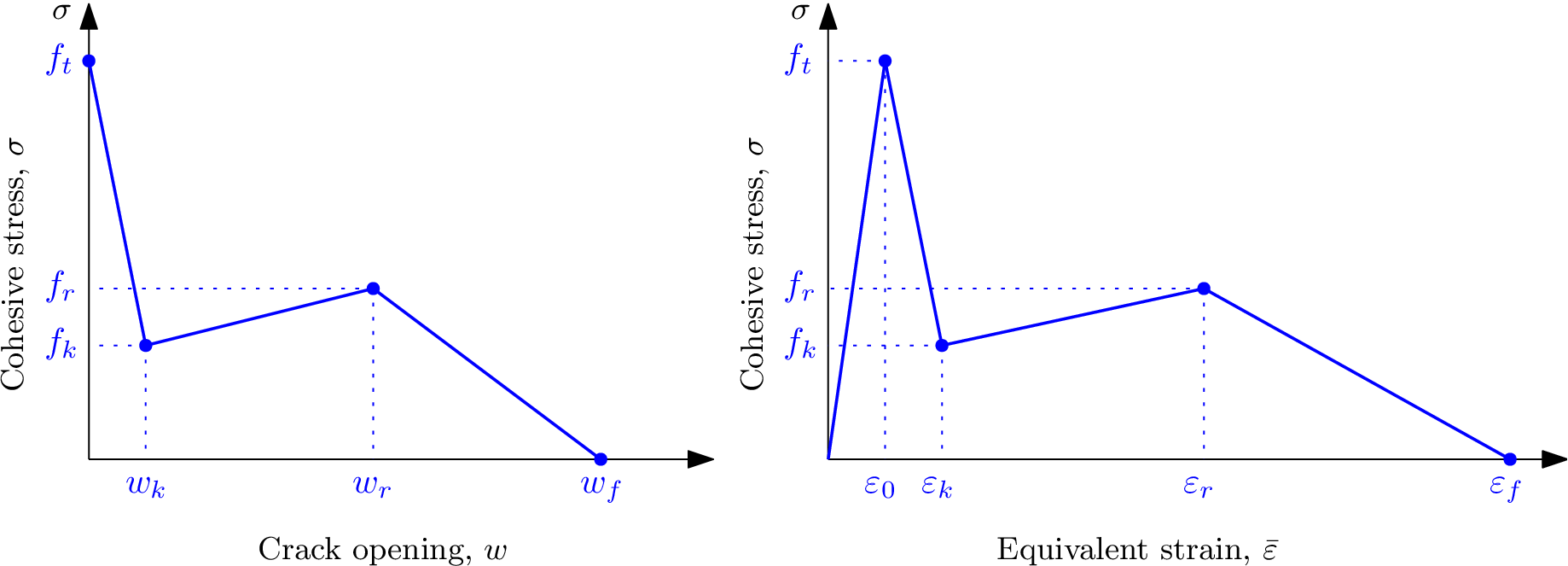
Fig. 6 Trilinear softening diagram expressed in terms of the crack opening (\(w\)) and expressed in terms of strain.
The inelastic strain \(\varepsilon_c\) is the difference between the total strain \(\varepsilon\) and the elastic strain \(\varepsilon/E\), thus:
If \(\sigma\) is obtained by using the damage parameter (\(\omega\)), it can be expressed as follows:
Therefore, the inelastic strain can be written as:
Thus, crack opening (\(w\)) is related to damage (\(\omega\)) through (Note that \(\omega\) represents damage and \(w\) represents crack opening.):
where \(h\) stands for the effective thickness of the crack band, which is estimated by projecting the finite element onto the direction of the maximum principal strain at the onset of damage.
Hereafter, the expressions of damage (\(\omega\)) are obtained for each section of the softening diagram (before damage develops, damage between points \(t\) and \(k\), between points \(k\) and \(r\), between points \(r\) and \(f\), and, finally, after damage has fully developed).
Case 1: :math:`varepsilon leq varepsilon_0`: In this case, damage has not started, thus:
\[\omega = 0\]And its derivative:
\[\dfrac{\partial \omega}{\partial \varepsilon} = 0\]Case 2: :math:`varepsilon_0 le varepsilon leq varepsilon_k`: Referred to the \(\sigma-w\) diagram:
\[\sigma = f_t + w \dfrac{f_k - f_t}{w_k}\]Therefore, since \(f_t = E \varepsilon_0\) and using expressions (34) and (35):
\[\omega = \dfrac{E}{E + h \left(\dfrac{f_k - f_t}{w_k}\right)} - \dfrac{E \varepsilon_0}{\varepsilon \left[E + h \left(\dfrac{f_k - f_t}{w_k}\right)\right]}\]And its derivative:
\[\dfrac{\partial \omega}{\partial \varepsilon} = \dfrac{E \varepsilon_0}{E + h \left(\dfrac{f_k - f_t}{w_k}\right)} \cdot \dfrac{1}{\varepsilon^2}\]Case 3: :math:`varepsilon_k le varepsilon leq varepsilon_r`: Referred to the \(\sigma-w\) diagram:
\[\sigma = f_k + (w - w_k) \left(\dfrac{f_r - f_k}{w_r - w_k}\right)\]Therefore, using expressions (34) and (35):
\[\omega = \dfrac{E}{E + h \left(\dfrac{f_r - f_k}{w_r - w_k}\right)} + \dfrac{1}{\varepsilon} \cdot \dfrac{w_k \left(\dfrac{f_r - f_k}{w_r - w_k}\right) - f_k}{E + h \left(\dfrac{f_r - f_k}{w_r - w_k}\right)}\]And its derivative:
\[\dfrac{\partial \omega}{\partial \varepsilon} = - \dfrac{w_k \left(\dfrac{f_r - f_k}{w_r - w_k}\right) - f_k}{E + h \left(\dfrac{f_r - f_k}{w_r - w_k}\right)} \cdot \dfrac{1}{\varepsilon^2}\]Case 4: :math:`varepsilon_r le varepsilon leq varepsilon_f`: Referred to the \(\sigma-w\) diagram:
\[\sigma = f_r + (w - w_r) \left(\dfrac{-f_r}{w_f - w_r}\right)\]Therefore, using expressions (34) and (35):
\[\omega = \dfrac{E}{E + h \left(\dfrac{-f_r}{w_f - w_r}\right)} + \dfrac{1}{\varepsilon} \cdot \dfrac{w_r \left(\dfrac{-f_r}{w_f - w_r}\right) - f_r}{E + h \left(\dfrac{-f_r}{w_f - w_r}\right)}\]And its derivative:
\[\dfrac{\partial \omega}{\partial \varepsilon} = - \dfrac{w_r \left(\dfrac{-f_r}{w_f - w_r}\right) - f_r}{E + h \left(\dfrac{-f_r}{w_f - w_r}\right)} \cdot \dfrac{1}{\varepsilon^2}\]Case 5: :math:`varepsilon geq varepsilon_f`: In this case, damage is fully developed:
\[\omega = 1\]
Note that parameter \(\it{damlaw}\) determines which type of damage law should be used, but the adjustment for element size is done only if parameter \(\it{wf}\) is specified for \(\it{damlaw}=0\) or \(\it{damlaw}=1\). For other values of \(\it{damlaw}\), or if parameter \(\it{ef}\) is specified instead of \(\it{wf}\), the stress-strain curve does not depend on element size and the model would exhibit pathological sensitivity to the mesh size. These cases are intended to be used in combination with a nonlocal formulation. An alternative formulation uses fracture energy to determine fracturing strain.
The model parameters are summarized in Table 26. Figure Fig. 7 shows three modes of a softening law with corresponding variables.
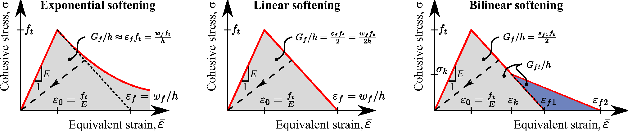
Fig. 7 Implemented stress-strain diagrams for isotropic damage material. Fracturing strain \(\varepsilon_f\) and crack opening at zero stress \(w_f\) are interrelated through effective thickness \(h\) of the crack band. Note that exponential softening approach based on an exponential cohesive law is not exactly equivalent to the approach based on an exponential softening branch of the stress-strain diagram; see the detailed discussion of the damage laws.
Description |
Isotropic damage model for concrete in tension |
Record Format |
Idm1 |
Parameters |
|
Supported modes |
3dMat, PlaneStress, PlaneStrain, 1dMat |
Features |
Adaptivity support |
Tests/Examples |
partests/bar/bar.oofem.in, sm/adapt01.in, sm/adapt02.in, sm/idm01.in, sm/idm02.in, sm/idm03.in, sm/idm04.in, sm/idm05.in, sm/idm06.in, sm/idm11.in (and 4 more) |
- param k:
Ratio between uniaxial compressive and tensile strength, needed only if equivstraintype=3, default value 1
- param damlaw:
Allows to choose from different damage laws:
0 - Exponential softening (default) with parameters e0 and wf \(|ef| |gf|\)
1 - Linear softening with parameters e0 and wf \(|ef| |gf|\)
2 - Bilinear softening with (e0, gf, gft, ek) \(|wk| |sk| |wf| |wkwf| |skft| |wk|\)
3 - Hordijk softening (not implemented yet)
4 - Mazars damage law with parameters At and Bt
5 - Smooth stress-strain curve with parameters e0 and md
6 - Disable damage (dummy linear elastic material)
7 - Extended smooth damage law \((`\)eq:damageEvol``)` with parameters ft, ep, e1, e2, nd
11 - Trilinear softening diagram with (e0, w_k, w_r, w_f, f_k, f_r)
- param e0:
Strain at peak stress (for damage laws 0,1,2,3), limit elastic strain (for damage law 4), characteristic strain (for damage law 5)
- param wf:
Parameter controlling ductility, has the meaning of crack opening (for damage laws 0 and 1)
- param ef:
Parameter controlling ductility, has the meaning of strain (for damage laws 0 and 1)
- param ek:
Strain at knee point in bilinear softening type (for damage law 2)
- param wk:
Crack opening at knee point in bilinear softening type (for damage law 2)
- param sk:
Stress at knee point in bilinear softening type (for damage law 2)
- param wkwf:
Ratio of wk/wf \(<0,1>\) in bilinear softening type (for damage law 2)
- param skft:
Ratio of sk/ft \(<0,1>\) in bilinear softening type (for damage law 2)
- param gf:
Fracture energy (for damage laws 0–2)
- param gft:
Total fracture energy (for damage law 2)
- param At:
Parameter of Mazars damage law, used only by law 4
- param Bt:
Parameter of Mazars damage law, used only by law 4
- param md:
Exponent used only by damage law 5, default value 1
- param ft:
Tensile strength, used only by damage law 7
- param ep:
Strain at peak stress, used only by damage law 7
- param e1:
Parameter used only by damage law 7
- param e2:
Parameter used only by damage law 7
- param nd:
Exponent used only by damage law 7
- param griff_n:
Uniaxial compression/tensile ratio for Griffith’s criterion
- param maxOmega:
Maximum damage, used for convergence improvement (its value is between 0 and 0.999999 (default), and it affects only the secant stiffness but not the stress)
- param checkSnapBack:
Parameter for snap back checking, 0 no check, 1 check (default)
- param w_k:
Crack opening of point k in the trilinear diagram (see Fig. 6)
- param w_r:
Crack opening of point r in the trilinear diagram (see Fig. 6)
- param w_f:
Crack opening of point f in the trilinear diagram (see Fig. 6)
- param f_k:
Cohesive stress of point k in the trilinear diagram (see Fig. 6)
- param f_r:
Cohesive stress of point r in the trilinear diagram (see Fig. 6)
Supported modes: 3dMat, PlaneStress, PlaneStrain, 1dMat
Features: Adaptivity support
Isotropic damage model for tensile failure – summary. :name: id_table
Nonlocal isotropic damage model for tensile failure - Idmnl1
Nonlocal version of isotropic damage model from Section Isotropic damage model for tensile failure - Idm1. The nonlocal averaging acts as a powerful localization limiter.
In the standard version of the model, damage is driven by the nonlocal equivalent strain \(\bar{\varepsilon}\), defined as a weighted average of the local equivalent strain:
In the “undernonlocal” formulation, the damage-driving variable is a combination of local and nonlocal equivalent strain, \(m\bar{\varepsilon}+(1-m)\tilde{\varepsilon}\), where \(m\) is a parameter between 0 and 1. (If \(m>1\), the formulation is called “overnonlocal”; this case is useful for nonlocal plasticity but not for nonlocal damage.)
Instead of averaging the equivalent strain, one can average the compliance variable \(\gamma\), directly related to damage according to the formula \(\gamma=\omega/(1-\omega)\).
The weight function \(\alpha\) contains a certain parameter with the dimension of length, which is in general called the characteristic length. Its specific meaning depends on the type of weight function. The following functions are currently supported:
Truncated quartic spline, also called the bell-shaped function,
\[\alpha_0(s) = \left\langle 1-\frac{s^2}{R^2}\right\rangle^2\]where \(R\) is the interaction radius (characteristic length) and \(s\) is the distance between the interacting points. This function is exactly zero for \(s\ge R\), i.e., it has a bounded support.
Gaussian function
\[\alpha_0(s) = \exp\left(-\frac{s^2}{R^2}\right)\]which is theoretically nonzero for an arbitrary large \(s\) and thus has an unbounded support. However, in the numerical implementation the value of \(\alpha_0\) is considered as zero for \(s>2.5R\).
Exponential function
\[\alpha_0(s) = \exp\left(-\frac{s}{R}\right)\]which also has an unbounded support, but is considered as zero for \(s>6R\). This function is sometimes called the Green function, because in 1D it corresponds to the Green function of the Helmholtz-like equation used by implicit gradient approaches.
Piecewise constant function
\[\begin{split}\alpha_0(s) =\left\{\begin{array}{cc} 1 & \mbox{ if } s\le R \\ 0 & \mbox{ if } s> R \end{array}\right.\end{split}\]which corresponds to uniform averaging over a segment, disc or ball of radius \(R\).
Function that is constant over the finite element in which point \(\mbf{x}\) is located, and is zero everywhere else. Of course, this is not a physically objective definition of nonlocal averaging, since it depends on the discretization. However, this kind of averaging was proposed in a boundary layer by Prof.Bažant and was implemented into OOFEM for testing purposes.
Special function
\[\alpha_0(s) =\int_{-\infty}^\infty \exp\left(-\frac{\sqrt{s^2+t^2}}{R}\right)\mbox{d}t\]obtained by reduction of the exponential function from 2D to 1D. The integral cannot be evaluated in closed form and is computed by OOFEM numerically. This function can be used in one-dimensional simulations of a two-dimensional specimen under uniaxial tension; for more details see [Gra14].
The above functions depend only on the distance \(s\) between the interacting points and are not normalized. If the normalizing condition
is imposed in an infinite body \(V_{\infty}\), it is sufficient to scale \(\alpha_0\) by a constant and set
where
Constant \(V_{r\infty}\) can be computed analytically depending on the specific type of weight function and the number of spatial dimensions in which the analysis is performed. Since the factor \(1/V_{r\infty}\) can be incorporated directly in the definition of \(\alpha_0\), this case is referred to as “no scaling”.
If the body of interest is finite (or even semi-infinite), the averaging integral can be performed only over the domain filled by the body, and the volume contributing to the nonlocal average at a point \(\mbf{x}\) near the boundary is reduced as compared to points \(\mbf{x}\) far from the boundary or in an infinite body. To make sure that the normalizing condition
holds for the specific domain \(V\), different approaches can be used. The standard approach defines the nonlocal weight function as
where
According to the approach suggested by Borino, the weight function is defined as
where \(\delta\) is the Dirac distribution. One can also say that the nonlocal variable is evaluated as
The term on the right-hand side after the integral is a multiple of the local variable, and so it can be referred to as the local complement.
In a recent paper [Gra14], special techniques that modify the averaging procedure based on the distance from a physical boundary of the domain or on the stress state have been considered. The details are explained in [Gra14]. These techniques can be invoked by setting the optional parameter nlVariation to 1, 2 or 3 and specifying additional parameters \(\beta\) and \(\zeta\) for distance-based averaging, or \(\beta\) for stress-based averaging.
The model parameters are summarized in Table 27 and Table 28.
Description |
Nonlocal isotropic damage model for concrete in tension |
Record Format |
Idmnl1 |
Parameters |
|
Tests/Examples |
partests/barnl/barnl.oofem.in, partests/barnl/barnl2.oofem.in, partests/brazil_2d_nl2/brazil_2d_nl.oofem.in, partests/lb03/lb03.oofem.in, sm/distancebasedaveraging.in, sm/stressbasedaveraging.in |
Description |
Nonlocal isotropic damage model for concrete in tension
|
Supported modes |
3dMat, PlaneStress, PlaneStrain, 1dMat |
Features |
Adaptivity support |
Anisotropic damage model - Mdm
Local formulation
Local formulation
The concept of isotropic damage is appropriate for materials weakened by voids, but if the physical source of damage is the initiation and propagation of microcracks, isotropic stiffness degradation can be considered only as a first rough approximation. More refined damage models take into account the highly oriented nature of cracking, which is reflected by the anisotropic character of the damaged stiffness or compliance matrices.
A number of anisotropic damage formulations have been proposed in the literature. Here we use a model outlined by Jirásek [mdm], which is based on the principle of energy equivalence and on the construction of the inverse integrity tensor by integration of a scalar over all spatial directions. Since the model uses certain concepts from the microplane theory, it is called the microplane-based damage model (MDM).
The general structure of the MDM
model is schematically shown in ff4
and the basic equations are summarized in Table 29.
Here, \(\veps\) and \(\vsig\) are the (nominal) second-order
strain and stress tensors
with components \(\eps_{ij}\) and \(\sigma_{ij}\); \(ě\) and \(š\)
are first-order strain and stress tensors with components \(e_i\)
and \(s_i\), which characterize the strain and stress on “microplanes”
of different orientations given by a unit vector \(\mbf{n}\)
with components \(n_i\);
\(\psi\) is a dimensionless compliance parameter
that is a scalar but can have different values for different
directions \(\mbf{n}\);
the symbol \(\delta\) denotes a virtual quantity; and a sumperimposed
tilde denotes an effective quantity, which is supposed to characterize the
state of the intact material between defects such as microcracks or voids.
\(\vet = \vepst \cdot \mbf{n}\) |
\(\vst = \psi š\) |
\(š = \vsig \cdot \mbf{n}\) |
\(\vsigt : \dvepst = \frac{3}{2\pi} \int_{\Omega} \vst \cdot \dvet \; \mbox{d}\Omega\) |
\(\dvs \cdot ě = d\vst \cdot \vet\) |
\(\dvsig : \veps = \frac{3}{2\pi} \int_{\Omega} \dvs \cdot ě \; d\Omega\) |
\(\vsigt = \frac{3}{2\pi} \int_\Omega (\vst \otimes \mbf{n}) \sym \; d\Omega\) |
\(ě = \psi \vet\) |
\(\veps = \frac{3}{2\pi} \int_\Omega (ě \otimes \mbf{n}) \sym \; d\Omega\) |
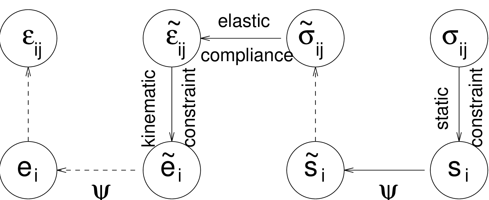
Fig. 8 Structure of microplane-based anisotropic damage model
Combining the basic equations, it is possible to show that the components of the damaged material compliance tensor are given by
where \(C^e_{pqrs}\) are the components of the elastic material compliance tensor,
are the components of the so-called damage effect tensor, and
are the components of the second-order inverse integrity tensor. The integration domain \(\Omega\) is the unit hemisphere. In practice, the integral over the unit hemisphere is evaluated by summing the contribution from a finite number of directions, according to one of the numerical integration schemes that are used by microplane models.
The scalar variable \(\psi\) characterizes the relative compliance in the direction given by the vector \(\mbf{n}\). If \(\psi\) is the same in all directions, the inverse integrity tensor evaluated from (47) is equal to the unit second-order tensor (Kronecker delta) multiplied by \(\psi\), the damage effect tensor evaluated from (46) is equal to the symmetric fourth-order unit tensor multiplied by \(\psi\), and the damaged material compliance tensor evaluated from (45) is the elastic compliance tensor multiplied by \(\psi^2\). The factor multiplying the elastic compliance tensor in the isotropic damage model is \(1/(1-\omega)\), and so \(\psi\) corresponds to \(1/\sqrt{1-\omega}\). In the initial undamaged state, \(\psi=1\) in all directions. The evolution of \(\psi\) is governed by the history of the projected strain components. In the simplest case, \(\psi\) is driven by the normal strain \(e_N=\eps_{ij}n_in_j\). Analogy with the isotropic damage model leads to the damage law
and loading-unloading conditions
in which \(\kappa\) is a history variable that represents the maximum level of normal strain in the given direction ever reached in the previous history of the material. An appropriate modification of the exponential softening law leads to the damage law
where \(e_0\) is a parameter controlling the elastic limit, and \(e_f>e_0\) is another parameter controlling ductility. Note that softening in a limited number of directions does not necessarily lead to softening on the macroscopic level, because the response in the other directions remains elastic. Therefore, \(e_0\) corresponds to the elastic limit but not to the state at peak stress.
If the MDM model is used in its basic form described above, the compressive strength turns out to depend on the Poisson ratio and, in applications to concrete, its value is too low compared to the tensile strength. The model is designed primarily for tensile-dominated failure, so the low compressive strength is not considered as a major drawback. Still, it is desirable to introduce a modification that would prevent spurious compressive failure in problems where moderate compressive stresses appear. The desired effect is achieved by redefining the projected strain \(e_N\) as
where \(m\) is a nonnegative parameter that controls the sensitivity to the mean stress, \(\sigma_{kk}\) is the trace of the stress tensor, and the normalizing factor \(Ee_0\) is introduced in order to render the parameter \(m\) dimensionless. Under compressive stress states (characterized by \(\sigma_{kk}<0\)), the denominator in ((49)) is larger than 1, and the projected strain is reduced, which also leads to a reduction of damage. A typical recommended value of parameter \(m\) is 0.05.
Nonlocal formulation
Nonlocal formulation of the MDM model is based on the averaging of the inverse integrity tensor. This roughly corresponds to the nonlocal isotropic damage model with averaging of the compliance variable \(\gamma=\omega/(1-\omega)\), which does not cause any spurious locking effects. In equation ((46)) for the evaluation of the damage effect tensor, the inverse integrity tensor is replaced by its weighted average with components
By fitting a wide range of numerical results, it has been found that the parameters of the nonlocal MDM model can be estimated from the measurable material properties using the formulas
where \(E\) is Young’s modulus, \(G_f\) is the fracture energy, \(f_t\) is the uniaxial tensile strength, \(m\) is the compressive correction factor, typically chosen as \(m=0.05\), and \(R\) is the radius of nonlocal interaction reflecting the internal length of the material.
paragraph{Input Record} The model description and parameters are summarized in Table 30.
Description |
MDM Anisotropic damage model Common parameters |
Record Format |
Mdm |
Parameters |
|
Nonlocal variant I |
|
Additional params |
|
Nonlocal variant II |
|
Additional params |
|
Local variant I |
|
Additional params |
|
Local variant II |
|
Additional params |
|
Supported modes |
3dMat, PlaneStress |
Features |
Adaptivity support |
Isotropic damage model for interfaces
The model provides an interface law which can be used to describe a damageable interface between two materials (e.g.between steel reinforcement and concrete). The law is formulated in terms of the traction vector and the displacement jump vector. The basic response is elastic, with stiffness kn in the normal direction and ks in the tangential direction.
Similar to other isotropic damage models, this model assumes that the stiffness degradation is isotropic, i.e., both stiffness moduli decrease proportionally and independently of the loading direction. The damaged stiffnesses are \(:param:\)kn`times(1-omega)` and \(:param:\)ks`times(1-omega)` where \(\omega\) is a scalar damage variable.
The damage evolution law is postulated in an explicit form, relating the damage variable \(\omega\) to the largest previously reached equivalent “strain” level, \(\kappa\).
The equivalent “strain”, \(\tilde\varepsilon\), is a scalar measure of the displacement jump vector. The choice of the specific expression for the equivalent strain affects the shape of the elastic domain in the strain space and plays a similar role to the choice of a yield condition in plasticity.
Currently, in the present implementation, the equivalent strain is given by
where \(\langle w_n\rangle\) is the positive part of the normal displacement jump (opening of the interface) and \(w_s\) is the norm of the tangential part of displacement jump (sliding of the interface). Parameter \(\beta\) is optional and its default value is 0, in which case damage depends on the opening only (not on the sliding).
The dependence of damage \(\omega\) on maximum equivalent strain \(\kappa\) is described by the following damage law which corresponds to exponential softening:
Here, \(\varepsilon_0=f_t/k_n\) is the value of equivalent strain at the onset of damage.
Note that if the interface is subjected to shear traction only (with zero or negative normal traction), the propagation of damage starts when the magnitude of the sliding displacement is \(\vert w_s\vert=\varepsilon_0/\sqrt{\beta}\), i.e., when the magnitude of the shear traction is equal to
So the ratio between the shear strength and tensile strength of the interface, \(f_s/f_t\), is equal to \(k_s/k_n\sqrt{\beta}\).
The model parameters are summarized in Table 31.
Description |
Isotropic damage model for concrete in tension |
Record Format |
isointrfdm01 |
Parameters |
|
Supported modes |
2dInterface, 3dInterface |
Features |
|
Tests/Examples |
Isotropic damage model for interfaces using tabulated data for damage
The model provides an interface law which can be used to describe a damageable interface between two materials (e.g., between steel reinforcement and concrete). The law is formulated in terms of the traction vector and the displacement jump vector. The basic response is elastic, with stiffness kn in the normal direction and ks in the tangential direction.
Similar to other isotropic damage models, this model assumes that the stiffness degradation is isotropic, i.e., both stiffness moduli decrease proportionally and independently of the loading direction. The damaged stiffnesses are kn\(\times(1-\omega)\) and ks\(\times(1-\omega)\) where \(\omega\) is a scalar damage variable.
The equivalent “strain”, \(\tilde\varepsilon\), is a scalar measure derived from the displacement jump vector. The choice of the specific expression for the equivalent strain affects the shape of the elastic domain in the strain space and plays a similar role to the choice of a yield condition in plasticity. Currently, in the present implementation, \(\tilde\varepsilon\) is equal to the positive part of the normal displacement jump (opening of the interface).
The damage evolution law is postulated in a separate file that should have the following format. Each line should contain one strain, damage pair separated by a whitespace character. The exception to this is the first line which should contain a single integer stating how many strain, damage pairs that the file will contain. The strains given in the file is defined as the equivalent strain minus the limit of elastic deformation. To find the damage for arbitrary strains linear interpolation between the tabulated values is used. If a strain larger than one in the given table is achieved the respective damage for the largest tabulated strain will be used. Both the strains and damages must be given in a strictly increasing order.
The model parameters are summarized in Table 32.
Description |
Isotropic damage model for concrete in tension |
Record Format |
isointrfdm02 |
Parameters |
|
Supported modes |
2dInterface, 3dInterface |
Features |