Material models specific to concrete
Mazars damage model for concrete - MazarsModel
This isotropic damage model assumes that the stiffness degradation is isotropic, i.e., stiffness moduli corresponding to different directions decrease proportionally and independently of direction of loading.
It introduces two damage parameters \(\omega_t\) and \(\omega_c\) that are computed from the same equivalent strain using two different damage functions \(g_t\) and \(g_c\). The \(g_t\) is identified from the uniaxial tension tests, while \(g_c\) from compressive test. The damage parameter for general stress states \(\omega\) is obtained as a linear combination of \(\omega_t\) and \(\omega_c\): \(\omega=\alpha_t g_t + \alpha_c g_c\), where the coefficients \(\alpha_t\) and \(\alpha_c\) take into account the character of the stress state.
The damaged stiffness tensor is expressed as \(\mbf{D}=(1-\omega)\mbf{D}^e\).
Damage evolution law is postulated in an explicit form, relating damage parameter and scalar measure of largest reached strain level in material, taking into account the principle of preserving of fracture energy \(G_f\). The equivalent strain, i.e., a scalar measure of the strain level is defined as norm from positive principal strains.
The model description and parameters are summarized in Table 33.
Description |
Mazars damage model for concrete |
Record Format |
MazarsModel |
Parameters |
|
Supported modes |
3dMat, PlaneStress, PlaneStrain, 1dMat |
Nonlocal Mazars damage model for concrete - MazarsModelnl
The nonlocal variant of Mazars damage model for concrete. Model based on nonlocal averaging of equivalent strain. The nonlocal averaging acts as a powerful localization limiter. The bell-shaped nonlocal averaging function is used. The model description and parameters are summarized in Table 34.
Description |
Nonlocal Mazars damage model for concrete |
Record Format |
MazarsModelnl |
Parameters |
|
Supported modes |
3dMat, PlaneStress, PlaneStrain, 1dMat |
CebFip78 model for concrete creep with aging - CebFip78
Implementation of aging viscoelastic model for concrete creep according to the CEB-FIP Model Code. The model parameters are summarized in Table 35.
CebFip78 material model – summary.
Description |
CebFip78 model for concrete creep with aging |
Record Format |
CebFip78 |
Parameters |
|
Supported modes |
3dMat, PlaneStress, PlaneStrain, 1dMat, 2dPlateLayer,2dBeamLayer, 3dShellLayer |
Double-power law model for concrete creep with aging - DoublePowerLaw
Implementation of aging viscoelastic model for concrete creep with compliance function given by the double-power law. The model parameters are summarized in Table 36.
Description |
Double-power law model for concrete creep with aging |
Record Format |
DoublePowerLaw |
Parameters |
|
Supported modes |
3dMat, PlaneStress, PlaneStrain, 1dMat, 2dPlateLayer,2dBeamLayer, 3dShellLayer |
Eurocode 2 model for concrete creep and shrinkage - EC2CreepMat
Implementation of aging viscoelastic model for concrete creep according to Eurocode 2 for concrete structures The model parameters are summarized in Table 37.
According to EC2, the compliance function is defined using the creep coefficient \(\varphi\) as
where \(E_{cm}\) is the mean elastic modulus at the age of 28 days and \(E(t')\) is the elastic modulus at the age of loading, \(t'\).
Current implementation supports only linear creep which is valid only for stresses below 0.45 of the characteristic compressive strength at the time of loading.
The elastic modulus at age \(t\) (in days) is defined as
where \(s\) is a cement-type dependent constant (0.2 for class R, 0.25 for class N and finally 0.38 for type S), and the mean secant elastic modulus at 28 days can be estimated from the mean compressive strength
where \(f_{cm,28}\) is in MPa and the resulting modulus is in GPa.
The creep coefficient is given by the expression from Annex B of the standard.
with
and
else
and \(t'_T\) is the temperature-adusted age according to B.9 in the code. It is computed automatically if string temperatureDependent appears in the input record.
The shrinkage deformation is additively split into two parts: drying shrinkage \(\varepsilon_{sh,d}\) and autogenous shrinkage \(\varepsilon_{sh,a}\). Drying shrinkage strain at time \(t\) is computed from
where \(t_0\) is the duration of curing, \(k_h\) is a thickness-dependent parameter and
with \(\alpha_{ds1} = 3\) for cement class S, 4 for class N, and 6 for class R, and \(\alpha_{ds2} = 0.13\) for cement class S, 0.12 for class N, and 0.11 for class R.
Autogenous shrinkage strain can be computed as
Description |
EC2CreepMat model for concrete creep and shrinkage |
Record Format |
EC2CreepMat |
Parameters |
|
Supported modes |
3dMat, PlaneStress, PlaneStrain, 1dMat, 2dPlateLayer,2dBeamLayer, 3dShellLayer |
Tests/Examples |
B3 and MPS models for concrete creep with aging
Model B3 is an aging viscoelastic model for concrete creep and shrinkage, developed by Prof. Bažant and coworkers. In OOFEM it is implemented in three different ways.
The first version, “B3mat”, is kept in OOFEM for compatibility. It is based on an aging Maxwell chain. The moduli of individual units in the chain are evaluated in each step using the least-squares method.
The second, more recent version, is referred to as “B3solidmat”. Depending on the specified input it exploits either a non-aging Kelvin chain combined with the solidification theory, or an aging Kelvin chain. It is extended to the so-called Microprestress-Solidification theory (MPS), which in this implementation takes into account only the effects of variable humidity on creep; the effects of temperature on creep are not considered. The underlying rheological chain consists of four serially coupled components. The solidifying Kelvin chain represents short-term creep; it is serially coupled with a non-aging elastic spring that reflects instantaneous deformation. Long-term creep is captured by an aging dashpot with viscosity dependent on the microprestress, the evolution of which is affected by changes of humidity. The last unit describes volumetric deformations (shrinkage and thermal strains). Drying creep is incorporated either by the “averaged cross-sectional approach”, or by the “point approach”.
MPS
The latest version is denoted as “MPS” and is based on the microprestress-solidification theory [Bazant-89-I] [Bazant-97-I] [JirHav14a]. The rheological model consists of the same four components as in “B3solidmat”, but now the implemented exponential algorithm is designed especially for the solidifying Kelvin chain, which is a special case of an aging Kelvin chain. This model takes into account both humidity and temperature effects on creep. Drying creep is incorporated exclusively by the so-called “point approach”. The model can operate in four modes, controlled by the keyword \(CoupledAnalysisType\). The first mode (\(CoupledAnalysisType = 0\)) solves only the basic creep and runs as a single problem, while the remaining three modes need to be run as a staggered problem with humidity and/or temperature analysis preceding the mechanical problem; both humidity and temperature fields are read when \(CoupledAnalysisType = 1\), only the field of relative humidity is taken into account when \(CoupledAnalysisType = 2\) and finally, only temperature when \(CoupledAnalysisType = 3\).
The basic creep is in the microprestress-solidification theory influenced by the same four parameters \(q_1\) - \(q_4\) as in the model B3. Values of these parameters can be estimated from the composition of concrete mixture and its compressive strength using the following empirical formulae:
Here, \(\bar{f_c}\) is the average compressive cylinder strength at age of 28 days [MPa], \(a\), \(w\) and \(c\) is the weight of aggregates, water and cement per unit volume of concrete [kg/m^3].
Spring
The non-aging spring stiffness represents the asymptotic modulus of the material; it is equal to \(1/q_1\).
Kelvin Chain
The solidifying Kelvin chain is composed of \(M\) Kelvin units with fixed retardation times \(\tau_{\mu}\), \(\mu = 1, 2, \dots, M\), which form a geometric progression with quotient 10. The lowest retardation time \(\tau_1\) is equal to \(0.3\; \text{begoftimeofinterest}\), the highest retardation time \(\tau_M\) is bigger than \(0.5\; \text{endoftimeofinterest}\). The chain also contains a spring with stiffness \(E_0^\infty\) (a special case of Kelvin unit with zero retardation time).
Moduli \(E_{\mu}^\infty\) of individual Kelvin units are determined such that the chain provides a good approximation of the non-aging micro-compliance function of the solidifying constituent, \(\Phi(t-t') = q_2 \ln \left( 1 + \left( \left(t-t' \right)/\lambda_0 \right)^n \right)\), where \(\lambda_0 = 1\) day and \(n = 0.1\).
The technique based on the continuous retardation spectrum leads to the following formulae:
Viscosities \(\eta_{\mu}^\infty\) of individual Kelvin units are obtained from the simple relation \(\eta_{\mu}^\infty=\tau_{\mu}/E_{\mu}^\infty\). A higher accuracy is reached if all retardation times are multiplied by the factor 1.35 and the last modulus \(E_M\) is divided by 1.2.
Solidification
The actual viscosities \(\eta_{\mu}\) and stiffnesses \(E_{\mu}\) of the solidifying chain change in time according to \(\eta_{\mu}(t) = v(t) \eta_{\mu}^\infty\) and \(E_{\mu}(t) = v(t) E_{\mu}^\infty\), where
is the volume growth function, and exponent \(m = 0.5\). In the case of variable temperature or humidity, the actual age of concrete \(t\) is replaced by the equivalent time \(t_e\), which is obtained by integrating \((`\)dtedt``)`.
Microprestress
Evolution of viscosity of the aging dashpot is governed by the differential equation
where \(h\) is the relative pore humidity, \(T\) is the absolute temperature [K], \(T_0 = 298\) K is the room temperature, and parameter \(p = 2\). Parameter \(k_T\) is different for monotonically increasing and for cyclic temperature, and is defined as
in which \(k_{Tm}\) [-] and \(k_{Tc}\) [-] are new parameters and \(T_{\max}\) is the maximum temperature attained in the previous history of the material point.
Equation ((52)) differs from the one presented in the original work; it replaces the differential equation for microprestress, which is not used here. The evolution of viscosity can be captured directly, without the need for microprestress. What matters is only the relative humidity and temperature and their rates. Parameters \(c_0\) and \(k_1\) of the original MPS theory are replaced by \(\mu_S = c_0 T_0^{p-1} k_1^{p-1} q_4 (p-1)^p\). The initial value of viscosity is defined as \(\eta(t_0) = t_0/q_4\), where \(t_0\) is age of concrete at the onset drying or when the temperature starts changing, in the present implementation it is set \(relMatAge\) which corresponds to the material age when the material is cast.
As mentioned above, under variable humidity and temperature conditions the physical time \(t\) in function \(v(t)\) describing evolution of the solidified volume is replaced by the equivalent time \(t_e\). In a similar spirit, \(t\) is replaced by the solidification time \(t_s\) in the equation describing creep of the solidifying constituent, and by the reduced time \(t_r\) in equation \(\frac{d \varepsilon_f}{d t_r} = \sigma / \eta(t)\) relating the flow strain rate to the stress.
Factors transforming the physical time \(t\) into \(t_e\), \(t_r\) and \(t_s\) are defined as follows:
Functions describing the influence of temperature have the form
motivated by the rate process theory. \(R\) is the universal gas constant and \(Q_e\), \(Q_r\), \(Q_s\) are activation energies for hydration, viscous processes and microprestress relaxation, respectively. Only the ratios \(Q_e/R\), \(Q_r/R\) and \(Q_s/R\) have to be specified.
Functions describing the influence of humidity have the form
where \(\alpha_e\), \(\alpha_r\) and \(\alpha_s\) are parameters.
At sealed conditions (or \(CoupledAnalysisType = 2\)) the auxiliary coefficients \(\beta_{eT} = \beta_{rT} = \beta_{sT} = 1\) while at room temperature (or with \(CoupledAnalysisType = 3\)) factors \(\beta_{e,h} = \beta_{r,h} = \beta_{s,h} = 1\).
Both the size effect on drying creep as well as its delay behind drying shrinkage can be addressed through parameter \(p\) in the governing equation mps_viscosity. In the experiments, the average (cross-sectional) drying creep is decreasing with specimen size. Unfortunately, for the standard value \(p=2\), the MPS model exhibits the opposite trend. For \(p = \infty\) the size effect disappears, and for \(p < 0\) it corresponds to the experiments. It should be noted that for negative or infinite values of \(p\) the underlying theory loses its original physical background.
If the experimental data of drying creep measured on different sizes are missing, the exponent \(p = \infty\) can be taken as a realistic estimate.
When parameter \(p\) is changed from its recommended value \(p = 2\) it is advantageous to rewrite the governing differential equation to the following form
with newly introduced parameters
With the “standard value” \(p = 2\) (reverted size effect) the new parameter \(\tilde{p}\) is also 2, for \(p < 0\) (correct size effect) \(\tilde{p} < 1\) and finally with \(p = \infty\) the first parameter \(\tilde{p} = 1\) and the second parameter \(k_3\) becomes dimensionless. The other advantage of \(\tilde{p} = 1\) is that the governing differential equation becomes linear and can be solved directly.
The rate of thermal strain is expressed as \(\dot{\varepsilon}_T = \alpha_T \dot{T}\) and the rate of drying shrinkage strain as \(\dot{\varepsilon}_{sh} = k_{sh} \dot{h}\), where both \(\alpha_T\) and \(k_{sh}\) are assumed to be constant in time and independent of temperature and humidity.
There are two options to simulate the autogenous shrinkage in the MPS material model. The first one is according to the B4 model
and the second one is proposed in the Model Code 2010
For the normally hardening cement, the ultimate value of the autogenous shrinkage can be estimated from the composition using the empirical formula of the B4 model
Similarly, in the Model Code, the ultimate shrinkage strain can be estimated from the mean concrete strength at the age of 28 days and from the cement grade
where \(\alpha_{as}\) is 600 for cement grades 42.5 R and 52.5 R and N, 700 for 32.5 R and 42.5 N and 800 for 32.5 N.
The model description and parameters are summarized in Table 38 for “B3mat”, in Table 39 for “B3solidmat”, and in Table 40 for “MPS”. Since some model parameters are determined from the composition and strength using empirical formulae, it is necessary to use the specified units (e.g.compressive strength always in MPa, irrespectively of the units used in the simulation for stress). For “B3mat” and “B3solidmat” it is strictly required to use the specified units in the material input record (stress always in MPa, time in days etc.). The “MPS” model is almost unit-independent, except for \(\bar{f}_c\) in MPa and \(c\) in kg/m3, which are used in empirical formulae.
Description |
B3 material model for concrete aging |
Record Format |
B3mat |
Parameters |
|
Supported modes |
3dMat, PlaneStress, PlaneStrain, 1dMat, 2dPlateLayer,2dBeamLayer, 3dShellLayer |
Tests/Examples |
For illustration, sample input records for the material considered in Example 3.1 of the creep book by Bažant and Jirásek is presented. The concrete mix is composed of 170 kg/m3of water, 450 kg/m3of type-I cement and 1800 kg/m3of aggregates, which corresponds to ratios \(w/c=0.3778\) and \(a/c=4\). The compressive strength is \(\bar{f}_c=45.4\) MPa. The concrete slab of thickness 200 mm is cured in air with initial protection against drying until the age of 7 days. Subsequently, the slab is exposed to an environment with relative humidity of 70%. The following input record can be used for the first version of the model (B3mat):
B3mat 1 n 0.2 d 0. talpha 1.2e-5 relMatAge 28. fc 45.4 cc 450. w/c 0.3778 a/c 4. t0 7. timefactor 1. alpha1 1. alpha2 1.2 ks 1. hum 0.7 vs 0.1 shmode 1
Parameter \(\alpha_1=1\) corresponds to type-I cement, parameter \(\alpha_2=1.2\) to curing in air, parameter \(k_s=1\) to an infinite slab. The volume-to-surface ratio is in this case equal to one half of the slab thickness and must be specified in meters, independently of the length units that are used in the finite element analysis (e.g., for nodal coordinates). The value of relMatAge must be specified in days. Parameter relMatAge 28. means that time 0 of the analysis corresponds to concrete age 28 days. If material B3mat is used, the finite element analysis must use days as the units of time (not only for relMatAge, but in general, e.g.for the time increments).
If only the basic creep (without shrinkage) should be computed, then the material input record reduces to following:
B3mat 1 n 0.2 d 0. talpha 1.2e-5 relMatAge 28. fc 45.4 cc 450. w/c 0.3778 a/c 4. t0 7. timefactor 1. shmode 0
B3 SOLID MAT
Parameters
nummaterial model numberdmaterial densitynPoisson ratiotalphacoefficient of thermal expansionmodeoptional parameter; if \(mode = 0\) (default), parameters \(q1-q4\) are predicted from composition of the concrete mixture (parameters \(fc\), \(cc\), \(w/c\), \(a/c\) and \(t0\) need to be specified). Otherwise values of parameters \(q1-q4\) are expected.EmoduliModeoptional parameter; analysis of retardation spectrum (\(=0\), default value) or least-squares method (\(=1\)) is used for evaluation of Kelvin units moduliMicroprestress\(0=\) basic creep; \(1=\) drying creep (must be run as a staggered problem with preceding analysis of humidity diffusion. Parametershmmust be equal to 3. The following parameters must be specified:c0,c1,tS0,w_h,ncoeff,a)
shmode shrinkage mode;
\(0\): no shrinkage;
\(1\): average shrinkage (the following parameters must be specified:
ks, vs, hum and additionally alpha1, alpha2 for \(mode = 0\)
and kt, EpsSinf, q5 for \(mode = 1\);
\(2\): point shrinkage (needed: es0, r, rprime, at), w_h, ncoeff, a;
\(3\): point shrinkage based on MPS theory (needed: parameter kSh or value of kSh can be approximately determined if following parameters are given: inithum, finalhum, alpha1, and alpha2)
begoftimeofinterest optional parameter; lower boundary of time interval with good approximation of the compliance function [day]; default 0.1 day
endoftimeofinterest optional parameter; upper boundary of time interval with good approximation of the compliance function [day]
timefactor scaling factor transforming the simulation time units into days
relMatAge relative material age [day]
fc 28-day mean cylinder compression strength [MPa]
cc cement content of concrete mixture [kg/m3]
w/c water to cement ratio (by weight)
a/c aggregate to cement ratio (by weight)
t0 age of concrete when drying begins [day]
q1, q2, q3, q4 parameters (compliances) of B3 model for basic creep [1/TPa]
c0 MPS theory parameter [MPa-1day-1]
c1 MPS theory parameter [MPa]
tS0 MPS theory parameter - time when drying begins [day]
w_h, ncoeff, a sorption isotherm parameters obtained from experiments [Pedersen, 1990]
ks cross section shape factor [-]
alpha1 optional shrinkage parameter - influence of cement type (optional parameter, default value is 1.0)
alpha2 optional shrinkage parameter - influence of curing type (optional parameter, default value is 1.0)
hum relative humidity of the environment [-]
vs volume to surface ratio [m]
q5 drying creep parameter [1/TPa]
kt shrinkage parameter [day/m2]
EpsSinf shrinkage parameter [10-6]
- param es0:
final shrinkage at material point
- param at:
coefficient relating stress-induced thermal strain and shrinkage
- param rprime, r:
coefficients
- param kSh:
influences magnitude of shrinkage in MPS theory [-]
- param inithum, finalhum:
[-], if provided, approximate value of \(kSh\) can be computed
Supported modes: 3dMat, PlaneStress, PlaneStrain, 1dMat, 2dPlateLayer, 2dBeamLayer, 3dShellLayer
B3solid creep and shrinkage model – summary.
|
|
Supported modes |
3dMat, PlaneStress, PlaneStrain, 1dMat, 2dPlateLayer, 2dBeamLayer, 3dShellLayer |
Additional parameters
depend on the specific type of analysis:
1. Computing basic creep only, shrinkage not considered, parameters \(q_i\) estimated from composition.
mode 0 fc 45.4 cc 450. w/c 0.3778 a/c 4.\\ t0 7. microprestress 0 shmode 0
2. Computing basic creep only, shrinkage not considered, parameters \(q_i\) specified by the user.
mode 1 q1 18.81 q2 126.9 q3 0.7494 q4 7.692\\ microprestress 0 shmode 0
3. Computing basic creep only, shrinkage handled using the sectional approach, parameters estimated from composition.
mode 0 fc 45.4 cc 450. w/c 0.3778 a/c 4. t0 7.\\ microprestress 0 shmode 1 ks 1. alpha1 1. alpha2 1.2 hum 0.7 vs 0.1
4. Computing basic creep only, shrinkage handled using the sectional approach, parameters specified by the user.
mode 1 q1 18.81 q2 126.9 q3 0.7494 q4 7.692\\
microprestress 0 shmode 1 ks 1. q5 326.7 kt  28025 EpsSinf 702.4 t0 7. hum 0.7 vs 0.1
5. Computing basic creep only, shrinkage handled using the point approach (B3), parameters specified by the user.
mode 1 q1 18.81 q2 126.9 q3 0.7494 q4 7.692\\
microprestress 0 shmode 2 es0 ... r ... rprime ... at ...
6. Computing drying creep, shrinkage handled using the point approach (MPS), parameters \(q_i\) estimated from composition.
mode 0 fc 45.4 w/c 0.3778 a/c 4. t0 7. microprestress 1 \\
shmode 3 c0 1. c1 0.2 tS0 7. w\_h 0.0476 ncoeff 0.182 a 4.867  kSh 1.27258e-003
- param mode:
optional parameter; if \(mode = 0\) (default), parameters \(q1-q4\) are predicted from the composition of the concrete mixture (parameters fc, cc, w/c, a/c, and stiffnessfactor need to be specified). Otherwise, values of parameters \(q1-q4\) are expected.
- param CoupledAnalysisType:
\(0 =\) basic creep; \(1 =\) (default) drying creep, shrinkage, temperature transient creep, and creep at elevated temperature; \(2 =\) drying creep, shrinkage; \(3 =\) temperature transient creep and creep at elevated temperature; for choice #1, 2, 3, the problem must be run as a staggered problem with preceding analysis of humidity and/or temperature distribution. Following parameters must be specified:
musork3(according to exponentp),kTm(compulsory for choice #3 otherwise optional).- param lambda0:
scaling factor equal to 1.0 day in time units of analysis (e.g. 86400 if the analysis runs in seconds).
- param begoftimeofinterest:
lower boundary of time interval with good approximation of the compliance function; default value = 0.01 \(\lambda0\).
- param endoftimeofinterest:
upper boundary of time interval with good approximation of the compliance function; default value = 10000. \(\lambda0\).
- param timefactor:
scaling factor, for mps material must be equal to 1.0.
- param relMatAge:
relative material age = age at time when the material is cast in the structure.
|
|
Supported modes |
3dMat, PlaneStress, PlaneStrain, 1dMat, 2dPlateLayer, 2dBeamLayer, 3dShellLayer |
Finally consider the same conditions for “MPS material”.
In all the examples below,
the input record with the material description can start by
mps 1 d 2420. n 0.2 talpha 12.e-6 referencetemperature 296.
Additional parameters depend on the specific type of analysis: 1. Computing basic creep only, shrinkage not considered, parameters \(q_i\) estimated from composition and simulation time in days and stiffnesses in MPa.
mode 0 fc 45.4 cc 450. w/c 0.3778 a/c 4. stiffnessFactor 1.e6
timefactor 1. lambda0 1. begoftimeofinterest 1.e-2
endoftimeofinterest 3.e4  relMatAge 28.  CoupledAnalysisType 0.
2. Computing basic creep only, shrinkage not considered, parameters \(q_i\) specified by user, simulation time in seconds and stiffnesses in Pa.
mode 1 q1 18.81e-12 q2 126.9e-12 q3 0.7494e-12 q4 7.6926e-12
timefactor 1. lambda0 86400. begoftimeofinterest 864.
endoftimeofinterest 2.592e9 relMatAge 2419200. CoupledAnalysisType 0.
3. Computing both basic and drying creep, parameters \(q_i\) specified by user, simulation time in seconds and stiffnesses in MPa.
mode 1 q1 18.81e-6 q2 126.9e-6 q3 0.7494e-6 q4 7.6926e-6
timefactor 1. lambda0 86400. begoftimeofinterest 864.
endoftimeofinterest 2.592e9  relMatAge 2419200. CoupledAnalysisType
1.
ksh 0.0004921875. t0 2419200. kappaT 0.005051 mus 4.0509259e-8
Final recommendations:
to simulate basic creep without shrinkage it is possible to use all three models
B3mat with \(shmode = 0\)
B3Solidmat with \(shmode = 0\) and \(microprestress = 0\)
MPS with \(CoupledAnalysisType = 0\)
to simulate drying creep with shrinkage using “sectional approach”, only the first material model (B3mat) is suitable can be used (with \(shmode = 1\))
to simulate drying creep without shrinkage using “sectional approach”, only the first material model (B3mat) is suitable (with \(shmode = 1\), \(mode = 1\) and \(EpsSinf = 0.0\))
to simulate drying creep with shrinkage using “point approach” according to B3 model there are two options:
B3mat (with \(shmode = 2\))
B3Solidmat (with \(shmode = 2\)) In order to suppress shrinkage set \(es0 = 0.0\)
to simulate drying creep with shrinkage using “point approach” according to MPS model there are two options:
B3Solidmat (with \(shmode = 3\))
MPS with \(CoupledAnalysisType = 1\)
In order to suppress shrinkage set \(kSh = 0.0\)
MPS damage model
This model extends the model based on the Microprestress-Solidification theory, described in previous section and summarized in Table 40 for “MPS”, by tensile cracking.
This extension uses the isotropic damage model with Rankine definition of the equivalent deformation defined as the biggest principal effective stress divided by the elastic modulus. The softening law cannot deal directly with the strain because due to creep strain increases and this would lead to further softening without additional loading.
Two different approaches are implemented. The first one, default, (#1) reduces the stiffness only in the directions of tension (in case the tensile strength is exceeded). A full stiffness is restored in compression and after unloading from tension.
The other approach (#2) is the standard isotropic damage model which reduces the stiffness equally in all directions independently of loading. This approach leads to faster convergence because the secant stiffness can be used instead of the incremental viscoelastic stiffness which must be used in the first approach. The second approach becomes useful when the loading is monotonic or when the benefit of the accelerated computation prevails over the consequences of the reduced/underestimated stiffness in compression.
Proper energy dissipation is guaranteed by the crack-band approach.
The following algorithm is used to compute the stress vector (in each time step and until the iteration criteria are met):
Compute effective stress
where \(\sigma_{\mathrm{eff},k}\) is the effective stress vector in the preceding step, \(\bar{E}_k\) is the incremental stiffness, \(\boldsymbol{D}_\nu\) is a unit stiffness matrix and \(\Delta \varepsilon_k\), \(\Delta \varepsilon_k''\), \(\Delta \varepsilon_{sh,k}\), \(\Delta \varepsilon_{T,k}\) are the increments of the total strain, strain due to creep, shrinkage strain (sum of drying and autogenous shrinkage) and thermal strain, respectively.
Compute principal effective stresses \(\sigma_{\mathrm{eff,1}}\), \(\sigma_{\mathrm{eff,2}}\), \(\sigma_{\mathrm{eff,3}}\)
Evaluate equivalent deformation
Evaluate corresponding damage
if \(\tilde \varepsilon > \varepsilon_0\)
where \(\varepsilon_{c,f} = \frac{G_f}{f_t \: h}\)
and \(h\) is the characteristic length of the finite element in the direction of the biggest principal stress.
Compute principal nominal stresses
- depth:
1
approach #1: for \(i = 1, 2, 3\) if \(\sigma_{\mathrm{eff},i} > 0\), \(\sigma_{i} = (1-\omega) \sigma_{\mathrm{eff},i}\) else \(\sigma_{i} = \sigma_{\mathrm{eff},i}\)
approach #2: for \(i = 1, 2, 3\) \(\sigma_{i} = (1-\omega) \sigma_{\mathrm{eff},i}\)
Construct the stress vector in the original configuration
where \(\boldsymbol{T}\) is the stress transformation matrix.
The tensile strength and fracture energy can be defined either as fixed, time-independent values (parameters \(ft\), \(gf\)) or as variable, depending on the equivalent hydration time \(t_e\). The latter case is activated by keyword \(timeDepFracturing\); tensile strength and fracture energy are then linked to the current value of the mean compressive strength using (slightly modified) formulae from the fib Model Code 2010.
For \(0 \: \mathrm{MPa} \leq f_{cm}(t) \leq 20\) MPa the tensile strength is computed from a linear function
which starts at the origin and at \(f_{cm}(t) = 20\) MPa connects to expression
which is valid for \(20 \: \mathrm{MPa} \leq f_{cm}(t) \leq 58\) MPa. Finally, for \(f_{cm}(t) > 58\) MPa
Following the guidelines from the Model Code 2010 (section 5.1.5.2), the fracture energy \(G_f\) can be estimated from the mean compressive strength at 28 days using an empirical formula
In this function, the mean compressive strength must be provided in MPa and the resulting fracture energy is in N/m.
The growth in fracture energy is approximately proportional to the tensile strength. The current value of fracture energy is very simply computed as
The development of the mean compressive strength in time is adopted entirely from the Model Code 2010 (see section 5.1.9.1)
where \(fib\_s\) is a cement-type dependent coefficient (0.38 for cement 32.5 N; 0.25 for 32.5 R and 42.5 N; 0.2 for 42.5 R and 52.5 N and R), \(t_e\) is the equivalent age and \(f_{cm,28}\) is the mean compressive strength at the age of 28 days.
For some concretes the prediction formulae do not provide accurate predictions, therefore it is possible to scale the evolution of tensile strength and fracture energy by providing their 28-day values ft28 and gf28.
The model description and parameters are summarized in Table 41.
Description |
MPS damage model for concrete creep with cracking (additionaly all parameters from Table :numref:`mps_table`) |
Record Format |
MPSDamMat [ |
Parameters |
|
Supported modes |
3dMat, PlaneStress, PlaneStrain |
Microplane model M4 - Microplane_M4
Model M4 covers inelastic behavior of concrete under complex triaxial stress states. It is based on the microplane concept and can describe softening. However, objectivity with respect to element size is not ensured – the parameters need to be manually adjusted to the element size. Since the tangent stiffness matrix is not available, elastic stiffness is used. This can lead to a very slow convergence when used within an implicit approach. The model parameters are summarized in Table 42.
Description |
M4 material model |
Record Format |
Microplane_M4 |
Parameters |
|
Supported modes |
3dMat |
Damage-plastic model for concrete - ConcreteDPM
This model, developed by Grassl and Jirásek for failure of concrete under general triaxial stress, is described in detail in [GraJir]. It belongs to the class of damage-plastic models with yield condition formulated in terms of the effective stress \(\bar{\vsig} = \mD_e : (\veps - \veps_p)\). The stress-strain law is postulated in the form
where \(\mD_e\) is the elastic stiffness tensor and \(\omega\) is a scalar damage parameter. The plastic part of the model consists of a three-invariant yield condition, nonassociated flow rule, and pressure-dependent hardening law. For simplicity, damage is assumed to be isotropic. In contrast to pure damage models with damage driven by the total strain, here the damage is linked to the evolution of plastic strain.
The yield surface is described in terms of the cylindrical coordinates in the principal effective stress space (Haigh-Westergaard coordinates), which are the volumetric effective stress \(\bar{\sigma}_{\rm V} = {I_1(\bar{\vsig})}/{3}\), the norm of the deviatoric effective stress \(\bar{\rho} = \sqrt{2 J_2(\bar{\vsig})}\), and the Lode angle \(\theta\) defined by the relation
where \(J_2\) and \(J_3\) are the second and third deviatoric invariants.
The yield function
depends on the effective stress (which enters in the form of cylindrical coordinates) and on the hardening variable \(\kappa_{\rm p}\) (which enters through a dimensionless variable \(q_{\rm h}\)). Parameter \(\fc\) is the uniaxial compressive strength.
Note that, under uniaxial compression characterized by axial stress \(\bar{\sigma}<0\), we have \(\bar{\sigma}_{\rm V}=\bar{\sigma}/3\), \(\bar{\rho}=-\sqrt{2/3}\,\bar{\sigma}\) and \(\bar{\theta}=60^o\). The yield function then reduces to \(f_{\rm p}=(\bar{\sigma}/\fc)^2-q_{\rm{h}}^2\). This means that function \(q_{\rm{h}}\) describes the evolution of the uniaxial compressive yield stress normalized by its maximum value, \(\fc\).
The evolution of the yield surface during hardening is presented in Fig. 9. The parabolic shape of the meridians (Fig. 9a) is controlled by the hardening variable \(q_{\rm h}\) and the friction parameter \(m_0\). The initial yield surface is closed, which allows modeling of compaction under highly confined compression. The initial and intermediate yield surfaces have two vertices on the hydrostatic axis but the ultimate yield surface has only one vertex on the tensile part of the hydrostatic axis and opens up along the compressive part of the hydrostatic axis. The deviatoric sections evolve as shown in Fig. 9b, and their final shape at full hardening is a rounded triangle at low confinement and almost circular at high confinement. The shape of the deviatoric section is controlled by the Willam-Warnke function
The eccentricity parameter \(e\) that appears in this function, as well as the friction parameter \(m_0\), are calibrated from the values of uniaxial and equibiaxial compressive strengths and uniaxial tensile strength.
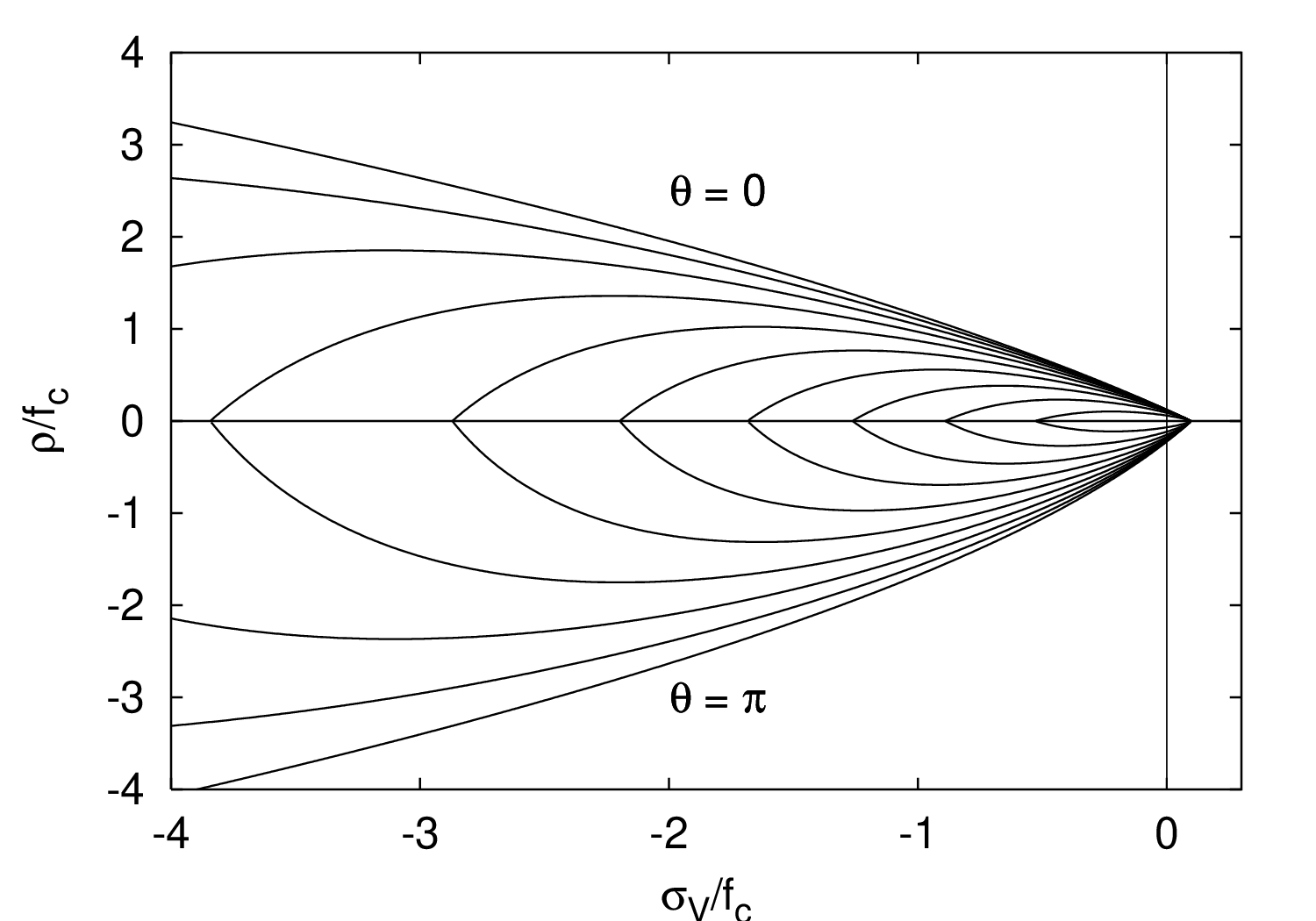
Fig. 9 Evolution of the yield surface during hardening: a) meridional section, b) deviatoric section for a constant volumetric effective stress of \(\bar{\sigma}_{\rm V} = -\fc/3\)
The maximum size of the elastic domain is attained when the variable \(q_{\rm h}\) is equal to one (which is its maximum value, as follows from the hardening law, to be specified in (73)). The yield surface is then described by the equation
The flow rule
is non-associated, which means that the yield function \(f_{\rm p}\) and the plastic potential
do not coincide and, therefore, the direction of the plastic flow \(\partial g_{\rm p}/\partial\bar{\vsig}\) is not normal to the yield surface. The ratio of the volumetric and the deviatoric parts of the flow direction is controlled by function \(m_{\rm g}\), which depends on the volumetric stress and is defined as
where \(A_{\rm g}\) and \(B_{\rm g}\) are model parameters that are determined from certain assumptions on the plastic flow in uniaxial tension and compression.
The dimensionless variable \(q_{\rm h}\) that appears in the yield function ((67)) is a function of the hardening variable \(\kappa_{\rm p}\). It controls the size and shape of the yield surface and, thereby, of the elastic domain. The hardening law is given by
The initial inclination of the hardening curve (at \(\kappa_{\rm p}=0\)) is positive and finite, and the inclination at peak (i.e., at \(\kappa_{\rm p} = 1\)) is zero.
The evolution law for the hardening variable, (In the original paper [GraJir], equation (:numref:)eq:dotkappap`) was written with \(\cos^2\bar{\theta}\) instead of \((2\cos\bar{\theta})^2\), but all the results presented in that paper were computed with OOFEM using an implementation based on ((74)).`, is given by:
This sets the rate of the hardening variable equal to the norm of the plastic strain rate scaled by a hardening ductility measure:
The dependence of the scaling factor \(x_{\rm{h}}\) on the volumetric effective stress \(\bar{\sigma}_{\rm V}\) is constructed such that the model response is more ductile under compression.
The variable
is a linear function of the volumetric effective stress.
Model parameters \(A_{\rm h}, B_{\rm h}, C_{\rm h}\) and \(D_{\rm h}\) are calibrated from the values of strain at peak stress under uniaxial tension, uniaxial compression and triaxial compression, whereas the parameters
are determined from the conditions of a smooth transition between the two parts of equation ((75)) at \(R_{\rm h} = 0\).
For the present model, the evolution of damage starts after full saturation of plastic hardening, i.e., at \(\kappa_{\rm p}=1\). This greatly facilitates calibration of model parameters, because the strength envelope is fully controlled by the plastic part of the model and damage affects only the softening behavior.
In contrast to pure damage models, damage is assumed to be driven by the plastic strain, more specifically by its volumetric part, which is closely related to cracking. To slow down the evolution of damage under compressive stress states, the damage-driving variable \(\kappa_{\rm d}\) is not set equal to the volumetric plastic strain, but it is defined incrementally by the rate equation
where
is a softening ductility measure. Parameter \(A_{\rm s}\) is determined from the softening response in uniaxial compression. The dimensionless variable \(R_{\rm s}=\dot{\varepsilon}_{\rm pV}^{-}/\dot{\varepsilon}_{\rm {pV}}\) is defined as the ratio between the “negative” volumetric plastic strain rate
and the total volumetric plastic strain rate \(\dot{\varepsilon}_{\rm {pV}}\). This ratio depends only on the flow direction \(\partial g_{\rm p}/\partial\bar{\vsig}\), and thus \(R_{\rm s}\) can be shown to be a unique function of the volumetric effective stress. In ((78)), \(\dot{\varepsilon}_{\rm{p}I}\) are the principal components of the rate of plastic strains and \(\left<\cdot\right>\) denotes the McAuley brackets (positive-part operator).
For uniaxial tension, for instance, all three principal plastic strain rates are nonnegative, and so \(\dot{\varepsilon}_{\rm pV}^{-} =0\), \(R_{\rm s}=0\) and \(x_{\rm s}=1\). This means that under uniaxial tensile loading we have \(\kappa_{\rm d}=\kappa_{\rm p}-1\). On the other hand, under compressive stress states the negative principal plastic strain rates lead to a ductility measure \(x_{\rm s}\) greater than one and the evolution of damage is slowed down. It should be emphasized that the flow rule for this specific model is constructed such that the volumetric part of plastic strain rate at the ultimate yield surface cannot be negative.
Description |
Damage-plastic model for concrete |
Record Format |
ConcreteDPM |
Parameters |
|
Supported modes |
3dMat |
Tests/Examples |
The relation between the damage variable \(\omega\) and the internal variable \(\kappa_{\rm d}\) (maximum level of equivalent strain) is assumed to have the exponential form
where \(\varepsilon_f\) is a parameter that controls the slope of the softening curve. In fact, equation ((79)) is used by the nonlocal version of the damage-plastic model, with \(\kappa_{\rm d}\) replaced by its weighted spatial average (not yet available in the public version of OOFEM). For the local model, it is necessary to adjust softening according to the element size, otherwise the results would suffer by pathological mesh sensitivity. It is assumed that localization takes place at the peak of the stress-strain diagram, i.e., at the onset of damage. After that, the strain is decomposed into the distributed part, which corresponds to unloading from peak, and the localized part, which is added if the material is softening. The localized part of strain is transformed into an equivalent crack opening, \(w\), which is under uniaxial tension linked to the stress by the exponential law
Here, \(f_t\) is the uniaxial tensile strength and \(w_f\) is the characteristic crack opening, playing a similar role to \(\varepsilon_f\). Under uniaxial tension, the localized strain can be expressed as the sum of the post-peak plastic strain (equal to variable \(\kappa_{\rm d}\)) and the unloaded part of elastic strain (equal to \(\omega f_t/E\)). Denoting the effective element size as \(h\), we can write
and substituting this into ((80)), we obtain a nonlinear equation
from which the damage variable \(\omega\) corresponding to the given internal variable \(\kappa_{\rm d}\) can be computed by Newton iteration. The effective element size \(h\) is obtained by projecting the element onto the direction of the maximum principal strain at the onset of cracking, and afterwards it is held fixed. The evaluation of \(\omega\) from \(\kappa_{\rm d}\) is no longer explicit, but the resulting load-displacement curve of a bar under uniaxial tension is totally independent of the mesh size. A simpler approach would be to use ((79)) with \(\varepsilon_f = w_f/h\), but then the scaling would not be perfect and the shape of the load-displacement curve (and also the dissipated energy) would slightly depend on the mesh size. With the present approach, the energy per unit sectional area dissipated under uniaxial tension is exactly \(G_f = w_f f_t\). The input parameter controling the damage law can be either the characteristic crack opening \(w_f\), or the fracture energy \(G_f\). If both are specified, \(w_f\) is used and \(G_f\) is ignored. If only \(G_f\) is specified, \(w_f\) is set to \(G_f/f_t\).
The onset of damage corresponds to the peak of the stress-strain diagram under proportional loading, when the ratios of the stress components are fixed. This is the case, e.g., for uniaxial tension, uniaxial compression, or shear under free expansion of the material (with zero normal stresses). However, for shear under confinement, the shear stress can rise even after the onset of damage, due to increasing hydrostatic pressure, which increases the mobilized friction. It has been observed that the standard approach leads to strong sensitivity of the peak shear stress to the element size. To reduce this pathological effect, a modified approach has been implemented. The second-order work (product of stress increment and strain increment) is checked after each step, and the element-size dependent adjustment of the damage law is applied only after the second-order work becomes negative. Up to this stage, the damage law corresponds to a fixed reference element size, which is independent of the actual size of the element. This size is set by the optional parameter href. If this parameter is not specified, the standard approach is used. For testing purposes, one can also specify the actual element size, helem, as a “material property”. If this parameter is not specified, the element size is computed for each element separately and represents its actual size.
The damage-plastic model contains 15 parameters, but only 6 of them need to be actually calibrated for different concrete types, namely Young’s modulus \(E\), Poisson’s ratio \(\nu\), tensile strength \(f_{\rm t}\), compressive strength \(f_{\rm c}\), parameter \(w_f\) (or fracture energy \(G_f\)), and parameter \(A_{\rm s}\) in the ductility measure ((77)) of the damage model. The remaining parameters can be set to their default values specified in [GraJir].
The model parameters are summarized in Table 43. Note that it is possible to specify the “size” of finite element, \(h\), which (if specified) replaces the actual element size in ((81)). The usual approach is to consider \(h\) as the actual element size (evaluated automatically by OOFEM), in which case the optional parameter \(h\) is missing (or is set to 0., which has the same effect in the code). However, for various studies of mesh sensitivity, it is useful to have the option of specifying \(h\) as an input “material” value.
If the element is too large, it may become too brittle and local snap-back occurs in the stress-strain diagram, which is not acceptable. In such a case, an error message is issued and the program execution is terminated. The maximum admis sible element size
happens to be equal to Hillerborg’s characteristic material length. For typical concretes it is in the order of a few hundred mm. If the condition \(h < h_{\max}\) is violated, the mesh needs to be refined. Note that the effective element size \(h\) is obtained by projecting the element. For instance, if the element is a cube of edge length 100 mm, its effective size in the direction of the body diagonal can be 173 mm.
Damage-plastic model for concrete - CDPM2
This model is an extension of the ConcreteDPM presented in Damage-plastic model for concrete - ConcreteDPM. CDPM2 has been developed by Grassl and coworkers for modelling the failure of concrete for both static and dynamic loading. It is is described in detail in [GraXenNys13]. The main differences between CDPM2 and ConcreteDPM are that in CDPM2
the plasticity part exhibits hardening once damage is active,
two independent damage parameters, which describe tensile and compressive damage, are introduced. These extensions provide more flexibility, and the shapes of stress-strain curves under various loading scenarios, including unloading, can be better adapted. The price to pay is an increased number of parameters and thus more difficult calibration.
CDPM2 deals with the same definition of effective stress as ConcreteDPM, namely
which means that the effective stress is computed using the plastic part of the model. The effect of damage is incorporated in the transformation from effective to nominal stress. While ConcreteDPM uses a simple reduction factor \(1-\omega\) (see (65)), CDPM2 splits the effective stress into the positive part, \(\bar{\boldsymbol{\sigma}}_{\rm t}\), and the negative part, \(\bar{\boldsymbol{\sigma}}_{\rm c}\), and then uses two damage variables, \(\omega_t\) and \(\omega_c\) (for tension and for compression). The nominal stress is thus evaluated as
The values of \(\omega_{\rm t}\) and \(\omega_{\rm c}\) range from 0 (undamaged) to 1 (fully damaged). The decomposition of the effective stress tensor into the positive and negative parts is based on principal values. If \(\bar{\sigma}_I\), \(I=1,2,3\), are the principal effective stresses and \(\boldsymbol{n}_I\), \(I=1,2,3\), are the corresponding principal directions, the effective stress tensor
is decomposed into
where \(\langle\ldots\rangle\) are Macaulay brackets (positive-part operator).
Let us now describe in more detail the plastic part of the model.
The yield condition is formulated in terms of the effective stress \(\bar{\boldsymbol{\sigma}}\) and therefore is unaffected by damage. The yield function is given by
where \(\bar\sigma_{\rm V}\) is the volumetric effective stress, \(\bar\rho\) is the norm of the deviatoric effective stress and \(\bar\theta\) is the Lode angle (another invariant of the effective stress tensor). Parameter \(f_{\rm c}\) is the uniaxial compressive strength. Evolution of the yield surface is controlled by two dimensionless stress-like hardening variables, \(q_{h1}\) and \(q_{h2}\), which are considered as functions of one dimensionless strain-like hardening variable, \(\kappa_p\).
The hardening laws read
During the initial stage of hardening, \(\kappa_p\) grows from 0 to 1, \(q_{h1}\) grows from its initial value \(q_{h0}\) to 1 while \(q_{h2}\) remains equal to 1. No damage is induced and the yield surface is expanding. A change of behavior occurs when \(\kappa_p\) becomes equal to 1. For the original ConcreteDPM model, there would not be any further evolution of the yield surface. In CDPM2, linear hardening with constant plastic modulus \(H_p\) is assumed. Variable \(q_{h1}\) remains equal to 1 while \(q_{h2}\) grows proportionally to the increments of \(\kappa_p\). If \(H_p\) is set to zero (i.e., \(q_{\rm h2}\) remains equal to 1), the same behavior as for the ConcreteDPM is obtained.
The shape of the deviatoric section is controlled by the Willam-Warnke function
Here, \(e\) is the eccentricity parameter.
The friction parameter \(m_0\) is given by
where \(f_{\rm t}\) is the tensile strength.
Hardening variable \(\kappa_p\) is a generalized form of cumulative plastic strain. Its rate corresponds to the rate of the norm of plastic strain rate scaled by a factor that depends on the stress state. This is described by the evolution equation
in which \(\bar{\sigma}_V\) is the hydrostatic part of effective stress and \(\bar{\theta}\) is the Lode angle. Function \(x_h\) has a complicated form, designed such that \(\kappa_p\) grows faster for positive hydrostatic stress and more slowly under negative hydrostatic stress. Consequently, the material response is brittle in tension and less brittle or even ductile in compression, especially under confinement. The form of function \(x_h\) suggested in [GraXenNys13] is
where
At the peak of the uniaxial compressive stress-strain curve, we have \(\bar{\sigma}_V=-f_c/3\) and thus \(R_h=0\). Positive values of \(R_h\) correspond to confined compression. Under compression with no confinement, \(x_h\) is equal to \(B_h\), and under high confinement it is close to \(A_h\). Parameter \(C_h\) controls the transition from \(B_h\) to \(A_h\) and if it is high, the transition occurs at higher compressive stresses. In this way, parameters \(A_h\), \(B_h\) and \(C_h\) can be used to tune up the sensitivity of the model to confining stresses. Parameter \(D_h\) affects the behavior under combined tension and compression, or under uniaxial or multiaxial tension.
Parameters \(E_h\) and \(F_h\) are not considered as independent.
To ensure a smooth transition between cases with positive and negative \(R_h\), they need to be set to \(E_h=B_h-D_h\) and \(F_h=(B_h-D_h)C_h/(A_h-B_h)\). Note that all these parameters are dimensionless. In [GraXenNys13] it was suggested to calibrate parameters \(A_h\), \(B_h\), \(C_h\) and \(D_h\) from the strains at peak stress under uniaxial tension, uniaxial compression and triaxial compression. Of course, four parameters cannot be uniquely determined from just three experimental values. It is desirable to use experimental data for triaxial compression at several levels of confinement. From the foregoing discussion of the role of individual parameters it follows that \(A_h\) should be greater than \(B_h\), to obtain a positive effect of confinement on ductility, and parameter \(D_h\) should be smaller than \(B_h\), to get a more brittle behavior in tension than in compression.
The flow rule is postulated in the non-associated format (Equation (70)) with a plastic potential given by the same expression (Equation (71)) as for the ConcreteDPM model, just with hardening variable \(q_h\) formally replaced by \(q_{h1}\). The direction of plastic flow is given by the gradient of the plastic potential, and it can be split into the volumetric and deviatoric parts:
Taking into account that \(\partial\bar{\sigma}_{\rm V}/\partial\bar{\boldsymbol{\sigma}}=\boldsymbol{\delta}/3\) and \(\partial\bar{\rho}/\partial\bar{\boldsymbol{\sigma}}=\bar{\mbf{s}}/\bar\rho\), restricting attention to the onset of the post-peak regime (in which \(q_{\rm h1} = q_{\rm h2} = 1\)) and differentiating the plastic potential (Equation (71)), we rewrite equation (Equation (90)) as
Since the flow rule is non-associative, the direction of the plastic flow is not normal to the yield surface. This is important for concrete since an associative flow rule would give an overestimated maximum stress for passive confinement.
Damage is initiated when the equivalent strain reaches the threshold \(\varepsilon_{0} = f_{\rm t}/E\), which represents the limit elastic strain under uniaxial tension. The evolution of damage variables depends on certain internal variables linked to the elastic and plastic strains computed using the plastic part of the model.
The tensile damage variable \(\omega_t\) is a function of three auxiliary internal variables, \(\kappa_{dt}\), \(\kappa_{dt1}\), and \(\kappa_{dt2}\).
Variable \(\kappa_{dt}\) is the maximum previously reached value of equivalent strain
where \(r\) is the function of the Lode angle specified in (86) and \(m_0\) is the friction parameter specified in (87).
Expression (92) has been derived from the yield condition \(f_{\rm p} = 0\) by setting \(q_{\rm {h1}}=1\) and \(q_{\rm{h2}} = \tilde{\varepsilon}/\varepsilon_{0}\), which leads to a quadratic equation.
Variables \(\kappa_{dt1}\) and \(\kappa_{dt2}\) are defined by the rate equations
where
is a ductility measure. For positive hydrostatic stress \(\bar\sigma_V\), we have \(\langle-\bar\sigma_V\rangle=0\) and \(x_s=1\). Under compression, \(x_s\) increases (provided that parameter \(A_s\) is greater than 1), which slows down the evolution of variables \(\kappa_{dt1}\) and \(\kappa_{dt2}\) and consequently of damage. For uniaxial compression, we have \(\bar\sigma_V/\bar\rho=-1/\sqrt{6}\) and formula (93) gives \(x_s=A_s\).
The specific form of the dependence of damage variable \(\omega_t\) on \(\kappa_{dt}\), \(\kappa_{dt1}\), and \(\kappa_{dt2}\) is dictated by the desired shape of the softening part of the uniaxial tensile stress-strain diagram. For instance, bilinear softening is obtained with
where \(\varepsilon_{f1}\) and \(\sigma_1\) is the strain and stress at the knee point of the softening diagram (where the two linear segments meet), and \(\varepsilon_{f}\) is the strain at which the stress vanishes. The choice of a bilinear softening diagram for tension makes it possible to obtain a steep initial descent followed by a long tail, which would not be that easy with the exponential diagram used in the ConcreteDPM model. In the local version of the model, objectivity with respect to mesh size must be enforced by adjustment of the softening diagram. Numerical parameters \(\varepsilon_{f1}\) and \(\varepsilon_{f}\) are then derived from material parameters \(w_{f1}\) and \(w_f\) that define the cohesive law in terms of the dependence of stress on crack opening, \(w\). Transformation of crack opening into the smeared cracking strain then leads to parameters \(\varepsilon_{f1}=w_{f1}/h\) and \(\varepsilon_{f}=w_f/h\) where \(h\) is the estimated thickness of the computationally resolved localized band.
The compressive damage variable \(\omega_c\) is a function of three auxiliary internal variables, \(\kappa_{dc}\), \(\kappa_{dc1}\), and \(\kappa_{dc2}\).
Variable \(\kappa_{dc}\) is defined by the rate equation
where \(\tilde\varepsilon\) is the already defined equivalent strain, and the scaling factor \(\alpha_c\) depends on the type of stress state and is given by
If all principal effective stresses \(\sigma_I\) are positive (or at least non-negative), we have \(\alpha_c=0\), and if all principal effective stresses are negative (or at least non-positive), we have \(\alpha_c=1\). For the zero stress state, \(\alpha_c\) is undefined, but for that particular state it is not needed.
Two other auxiliary internal variables that affect compressive damage are defined by the rate equations
where factor
depends on the plastic hardening variable \(q_{h2}\) and effective stress invariant \(\bar\rho\) and provides a smooth transition from pure damage to damage-plastic softening, which can occur during cyclic loading. The dependence of the compressive damage \(\omega_c\) on the internal variables is defined such that the relation between the stress and the inelastic strain, \(\varepsilon_{\rm i}\), under uniaxial compression is exponential and is given by
where \(\varepsilon_{\rm fc}\) is a parameter controls the initial inclination of the softening curve. The inelastic strain is defined as the difference between the total strain, \(\varepsilon\), and the elastic strain, \(\sigma/E\). Replacing \(\sigma\) by the right-hand side of ((98)), we obtain a nonlinear equation
from which \(\varepsilon_{\rm i}\) can be evaluated iteratively if the total strain \(\varepsilon\) is given. The use of different damage evolution rules for tension and compression is one important improvement over ConcreteDPM. In contrast to tension, the evolution law for compressive damage is considered to be independent of the element size, since compressive failure is often characterized by mesh-independent zones of damage growth.
parameter |
OOFEM identifier |
unit |
default |
meaning |
|---|---|---|---|---|
\(E\) |
E |
Pa |
Young’s modulus |
|
\(\nu\) |
n |
Poisson’s ratio |
||
\(f_t\) |
ft |
Pa |
uniaxial tensile strength |
|
\(f_c\) |
fc |
Pa |
uniaxial compression strength |
|
\(w_f\) |
wf |
m |
critical crack opening |
|
\(e\) |
ecc |
0.525 |
||
\(q_{h0}\) |
kinit |
0.3 |
initial value of hardening variable \(q_{h1}\), eq.~((84)) |
|
\(H_p\) |
hp |
0.5 |
hardening modulus (for the last stage, eq.~((85))) |
|
\(D_f\) |
dilation |
0.85 |
dilation factor, eq.~((97)) |
|
\(A_h\) |
Ahard |
0.08 |
hardening parameter, eq.~((89)) |
|
\(B_h\) |
Bhard |
0.003 |
hardening parameter, eq.~((89)) |
|
\(C_h\) |
Chard |
2 |
hardening parameter, eq.~((89)) |
|
\(D_h\) |
Dhard |
\(10^{-6}\) |
hardening parameter, eq.~((89)) |
|
\(A_s\) |
Asoft |
15 |
softening parameter, eq.~((78)) |
|
\(\varepsilon_{fc}\) |
efc |
\(10^{-4}\) |
softening parameter for compression, eq.~((98)) |
|
stype |
1 |
type of softening (1=bilinear) |
||
\(w_{f1}/w_f\) |
wf1 |
0.15 |
softening parameter for tension |
|
\(\sigma_1/f_t\) |
ft1 |
0.3 |
softening parameter for tension, eq.~((94)) |
From the presented description of the model equations, it is clear that CDPM2 uses a large number of parameters. In [GraXenNys13] it was recommended to adjust only a few basic parameters, most of which have a certain physical meaning, and to set all the other parameters to their default values. The physical parameters that can be adjusted depending on the specific type of concrete are Young’s modulus, Poisson’s ratio, uniaxial tensile and compression strengths, and the critical crack opening, which controls the tensile fracture energy. A summary of all model parameters and of their recommended default values is provided in Table Table 44. The table shows the symbol used for the parameter in equations describing the theoretical background and also the corresponding identifier used in OOFEM input files.
Parameters listed on the first five lines of Table Table 44 must be specified by the user. Parameter \(w_f\) corresponds to the opening of a cohesive crack at which the stress transmitted by the crack vanishes. It is closely related to the tensile fracture energy, \(G_{Ft}\). The shape of the cohesive curve for tensile failure is affected by the choice of the type of softening. The default choice is bilinear softening, which requires, in addition to \(f_t\) and \(w_f\), two more parameters that control the position of the point at which the slope of the diagram changes. This point is characterized by crack opening \(w_{f1}\) and stress \(\sigma_1\), but the input parameters for OOFEM are dimensionless ratios \(w_{f1}/w_f\) and \(\sigma_1/f_t\) with default values 0.15 and 0.3. In general, the fracture energy is evaluated as \(G_{Ft}=(f_tw_{f1} +\sigma_1 w_f)/2\), and for the default values this gives \(G_{Ft}=f_tw_f/4.444\), which means that parameter \(w_f\) can be evaluated from the tensile strength and fracture energy using formula \(w_f=4.444\,G_{Ft}/f_t\).
The eccentricity parameter \(e\) could be evaluated from \(f_t\) and \(f_c\) combined with the biaxial compression strength, \(f_{bc}\), using formula
where
The default value is not mentioned in [GraXenNys13]; in OOFEM it is taken as \(e=0.525\).
Parameter \(H_p\) is a dimensionless hardening modulus that sets the ratio between the increments of variables \(q_{h2}\) and \(\kappa_p\) during the last stage of the plastic hardening process. The value recommended in [GraXenNys13] is \(H_p=0.01\), but the default value used in OOFEM is 0.5.
The dilation parameter \(D_f\) controls the ratio between the transversal and axial plastic strain rates in uniaxial compression and thus can be used to control the volumetric expansion in the softening regime. The default value is set to 0.85, as suggested in [GraJir], which means that the transversal plastic strain rate will be \(-0.85\) times the (negative) axial plastic strain rate.
The default values of \(q_{h0}=0.3\), \(A_h=0.08\), \(B_h=0.003\), \(C_h=2\), \(D_h=10^{-6}\) and \(\varepsilon_{fc}=10^{-4}\) are taken from [GraXenNys13]. Parameter \(A_s\) was varied in [GraXenNys13] in the range from 1.5 to 15. In OOFEM, the default value of \(A_s\) is taken as 15, which was recommended in [GraJir].
Concrete is strongly \(\bf{rate-dependent}\). If the loading rate is increased, the tensile and compressive strength increase and are more prominent in tension than in compression. The dependency of the stress-strain response on the dynamic increase factor is taken into account by an additional variable \(\alpha_{\rm r}\). The rate dependency is included by scaling both the equivalent strain rate and the inelastic strain. The rate parameter is defined by
where \(X\) is the continuous compression measure (= 1 means only compression, = 0 means only tension).
The dynamic increase factor (DIF) for strength is computed according to Model Code 2010.
If sratetype is greater than zero, the strengths depend on the strain rate. A rate factor \(r\) is computed at the end of each step from the rates of the maximum and minimum principal strains, using the dynamic increase factors of the Model Code 2010 for tension (\(r_{\rm t}\)) and compression (\(r_{\rm c}\)), which are combined as \(r = (1-\alpha) r_{\rm t} + \alpha r_{\rm c}\). This rate factor is used in the next step. During unloading, the rate factors in tension and compression are kept constant, and once damage has started, the rate factor is no longer changed. Both \(f_{\rm t}\) and \(f_{\rm c}\) are multiplied by \(r\), which expands the yield surface without changing its shape. This is implemented by evaluating the model for the strains divided by \(r\) and multiplying the resulting stress by \(r\). Consequently, damage starts when the effective stress reaches the expanded yield surface, and the strains at peak stress increase with \(r\). The fracture energy is increased by \(r^n\), where \(n\) is given by erateexp. Since the strength increase is obtained by the plasticity part, the hardening modulus \(H_p\) does not need to be increased for rate dependent analyses.
The \(\bf{parameters of CDPM2}\) for OOFEM input file are summarised in Table 45. By default, two damage variables are used, i.e., the effective stress is transformed into nominal stress using equation ((82)). If parameter damflag is set to 3, only \(\omega_t\) is used and the effective stress is reduced by \(1-\omega_t\).
Description |
CDPM2 |
Record Format |
con2dpm |
Parameters |
|
Supported modes |
3dMat, PlaneStress, PlaneStrain, 1dMat |
Tests/Examples |
sm/con2dpm1.in, sm/con2dpm10.in, sm/con2dpm2.in, sm/con2dpm3.in, sm/con2dpm4.in, sm/con2dpm5.in, sm/con2dpm6.in, sm/con2dpm7.in, sm/con2dpm8.in, sm/con2dpm9.in (and 2 more) |
CDPM2F
CDPM2F is a fibre extension of CDPM2 in Damage-plastic model for concrete - CDPM2. The theory of CDPM2F is described in [ZhoMarGra24].
The main idea of CDPM2F is to adjust the damage part of CDPM2 to predict the effect of fibres.
Below in Table Table 46 the input parameters of CDPM2F in addition to those required for CDPM2 are described. CDPM2F requires exponential softening of the matrix (stype 2).
The dispersion factor \(\alpha\) describes how uniformly the fibres are distributed. It reduces the effective fibre volume fraction to \(v_{\rm f} = (1 + \ln \alpha)\, v_{\rm f0}\), so \(\alpha = 1\) corresponds to a uniform distribution. \(\alpha\) must lie between a lower limit \(\alpha_{\rm min}\), which follows from the other parameters (at \(\alpha_{\rm min}\) the fibres just carry the tensile strength of the matrix, so the response no longer hardens), and 1. If the input alpha is smaller than \(\alpha_{\rm min}\), the analysis stops with an error message that gives \(\alpha_{\rm min}\).
The dispersion factor can vary in space through the optional parameters [randvars (ia)] and [randgen (ia)] with the property identifier 1001, for example randvars 1 1001 randgen 1 2. When the material status of an integration point is created, function 2 (typically an InterpolatingFunction reading a random field from a file) is evaluated at the global coordinates of the point, and the result is used as a factor on the mean value alpha, as for the random fields of the lattice materials. The field should therefore have a mean of 1, and the coefficient of variation of the field is the coefficient of variation of \(\alpha\). Outside the grid of an InterpolatingFunction the factor is 1. Since \(\alpha_{\rm min}\) and 1 bound \(\alpha\), values of the product outside this range are set to the nearest limit at each integration point; for a wide distribution this changes the effective mean and coefficient of variation of \(\alpha\).
Description |
CDPM2F |
Record Format |
cdpm2f |
Parameters |
|
Supported modes |
3dMat, PlaneStrain, 1DMat |
Tests/Examples |
Fixed crack model for concrete - ConcreteFCM
Implementation of a fixed crack model. Uncracked material is modeled as isotropic linear elastic characterized by Young’s modulus and Poisson’s ratio. Cracking is initiated when principal stress reaches tensile strength. Further loading is governed by a softening law. Proper amount energy dissipation is guaranteed by the crack-band approach.
Multiple cracking is allowed; the maximum number of allowed cracks is controlled by :ncracks: parameter. Only mutually perpendicular cracks are supported. If cracking occurs in more directions, the behavior on the crack planes is considered to be independent.
The secant stiffness is used for unloading and reloading. In a compression regime, this model correspond to an isotropic linear elastic material.
The model supports 3 different options for stiffness reduction in shear after cracking, 2 options for the limit of the maximum shear stress on a crack plane and 6 different laws for postpeak behavior. The model parameters are summarized in Table 47.
ConcreteFCM 1 d 24.e-3 talpha 12.e-6 E 20000.~n 0.2 Gf 100e-6 ft 2.0 softType 2 shearType 1 beta 0.05 shearStrengthType 2 fc 30 ag 0.01\ lengthscale 1.~multipleCrackShear
Description |
Fixed crack model for concrete |
Record Format |
ConcreteFCM |
Parameters |
|
Supported modes |
3dMat, PlaneStress, PlaneStrain |
Tests/Examples |
ConcreteFCMViscoelastic
The material model “ConcreteFcmViscoelastic” has been developed in order to realistically capture the time-dependent behavior of cementitious materials with the possibility of tensile cracking. The model allows to link an arbitrary viscoelastic material model present in OOFEM with the model “ConcreteFCM” for tensile failure with fixed (not rotating) orientation of cracks developed for concrete. The material model assumes an additive split of the total deformation into the viscoelastic and cracking part. The viscoelastic material handles the stress-independent strains, i.e. shrinkage and thermal dilation.
Incremental stiffness matrix
In the case of an elastic (initial) stiffness or uncracked material, the stiffness matrix \(\bar{\mbf{D}}_{ve}\) is evaluated as the product of incremental stiffness of the viscoelastic material \(\bar{E}\) and the unit elastic stiffness matrix \(\mbf{D}_v\). The evaluation of the incremental modulus \(\bar{E}\) is computationally demanding, therefore within one time step it is stored in the material status. The value of stiffness depends on the history of relative humidity and temperature at given Gauss point and depends entirely on the viscoelastic material.
Secant stiffness matrix is obtained by adding the secant compliance of the cohesive cracks to the viscoelastic compliance matrix and by subsequent inversion of the result.
Tangent stiffness matrix is computed as
where \(\mbf{D}_{cr}\) is the tangent stiffness of the cracked material.
The secant and tangent matrix are constructed in the local
coordinate system corresponding to the orientation of the cracks and
then are rotated to the global
coordinate system. The individual components of \(\mbf{D}_{cr}\) are managed by
the ConcreteFCM material model.
Algorithm for stress evaluation
The stress evaluation algorithm can be decomposed into 3 subsequent steps:
Call the viscoelastic material to compute the stress-dependent strain increment
where \(\Delta \varepsilon\) is the total strain increment, \(\Delta \varepsilon''\) is the strain increment due to creep, \(\Delta \varepsilon_{sh}\) is the shrinkage increment, and \(\Delta \varepsilon_T\) is the thermal dilation increment.
Call the fixed-crack material to compute the new stress vector \(\sigma_{i+1}\) fulfilling the nonlinear equation
where \(\sigma_{i}\) is the old stress vector and \(\Delta \varepsilon_{cr}\) is the increment of crack strain, and update the new crack strain vector
Pass the difference of the total strain and the cracking strain to the viscoelastic material and perform a regular viscoelastic step.
Before the onset of cracking, the material is modeled as isotropic linear viscoelastic characterized by its compliance function, Poisson’s ratio, and the evolution of shrinkage which can depend both on equivalent time and change in relative humidity provided that the problem is solved as coupled.
Cracking is initiated when principal stress reaches tensile strength. Further loading is governed by a softening law. Proper amount energy dissipation is guaranteed by the crack-band approach, the width of the crack band is given by the size of the finite element projected in the direction of the principal stress.
Multiple cracking is allowed, the maximum number of cracks is controlled by ncracks parameter. Only mutually perpendicular cracks are supported. If cracking occurs in more directions, the behavior on the crack planes is considered to be independent.
The secant stiffness is used for unloading and reloading. In compression regime full stiffness is restored.
It is worth emphasizing that the status of the viscoelastic material tracks and keeps only a part of the total deformation equal to the difference of the total strain and the cracking strain.
Evolution of tensile strength and fracture energy
The current implementation supports both constant and time-evolving
values of tensile strength and fracture energy.
Constant values are used when the keyword timeDepFracturing
is missing in the definition of the material. Then, the values are taken directly from the
ConcreteFCM material (keywords ft and gf).
On the other hand, when the flag timeDepFracturing is present
in the material definition, the tensile strength and fracture energy
is time-evolving. In that case, the values of ft and gf
are ignored, and the value of parameter \(s\) (fib_s), and the mean
value of the compressive strength \(f_{cm,28}\) (fcm28) need to be
provided and serve for the prediction of \(f_t(t)\) and \(G_F(t)\).
Yet, it is possible to
override the predicted 28-day values by providing the fields
ft28 and gf28.
It must be noted that once the tensile stress exceeds the current value of tensile strength, the time development of the properties is terminated on the particular crack plane.
Mean value of the uniaxial compressive strength at specific time which is used for evaluation of the tensile strength and fracture energy is computed using expressions (5.1-50) and (5.1-51) in fib MC2010 [fib:2010]:
in which \(s\) is a coefficient reflecting cement type (table 5.1-9), \(t_e\) is the equivalent time from the viscoelastic model, and \(f_{cm,28}\) is the mean value of the uniaxial compressive strength at the age of 28 days.
The current value of tensile strength \(f_{ctm}(t)\) at time \(t\) is computed from the compressive strength at the corresponding age, similarly to section 5.1.5.1 in MC2010. The difference is that in MC2010, both tensile strength and fracture energy are treated as non-aging and are evaluated from \(f_{cm,28}\).
In the following expressions, \(f_{cm}\) and \(f_{ctm}\) are in MPa.
The value of fracture energy at the age of 28 days is computed according to section 5.1.5.2 in MC2010
In this equation, \(G_F\) is in N/m and the compressive strength is in MPa.
Here, the time development of fracture energy is chosen to be the same as the tensile strength
Description |
Viscoelastic fixed crack model for concrete |
Record Format |
ConcreteFCMViscoelastic |
Parameters |
|
Supported modes |
3dMat, PlaneStress, PlaneStrain |
Tests/Examples |
The viscoelastic material can be defined, for example, by the following listing. Note that the coefficient of thermal expansion is zero in ConcreteFcmViscoelastic and nonzero in the viscoelastic material that handles all stress-independent strains. Also note that the same values of the Poisson’s ratio are used.
mps 2 d 24.e-3 n 0.2 talpha 12.e-6 referencetemperature 296. mode 0 fc 30. cc 340. w/c 0.523 a/c 5.28 stiffnessfactor 1.e6 timefactor 1. lambda0 1. begoftimeofinterest 1.e-6 endoftimeofinterest 1.e4 relMatAge 7. CoupledAnalysisType 2 ksh 0.0 k3 35. p 1000.
Fixed crack model for fiber reinforced composites - FRCFCM
This material model is an extension of the ConcreteFCM described in Fixed crack model for concrete - ConcreteFCM.
It is possible to choose from three different “classes” of fibers. This choice is controlled by the keyword fiberType: 0 = continuous aligned fibers (CAF), 1 = short aligned fibers (SAF), and 2 = short random fibers (SRF). Currently, it is not possible to combine more classes of fibers in one material model.
All of the above-mentioned fiber types are further defined by the material properties and geometry. Fiber quantity is captured by the dimensionless volume fraction Vf (as a decimal). All fibers are assumed to have a circular cross-section (shape factor for shear kfib with a default value of 0.9) and to possess the same geometry characterized by the diameter Df and length Lf.
The overall elastic stiffness of the fiber-reinforced composite is calculated as a weighted average of the moduli of the matrix \(E_m\) and the fibers \(E_f\), and the Poisson’s ratio is considered to be equal to the Poisson’s ratio of the matrix. Similarly to ConcreteFCM, cracking is initiated once the tensile stress \(\sigma\) in the matrix reaches the tensile strength \(f_t\).
The nominal bridging stress for continuous aligned fibers which are not perpendicular to the crack plane \(\sigma_{b,f,\theta}\) can be very easily obtained by multiplying the nominal bridging stress for perpendicular fibers \(\sigma_{b,f}\) by two terms: the first one reflecting the lower volume of inclined fibers passing through the crack plane and the second one capturing the snubbing effect:
where \(f\) is a snubbing coefficient.
For the CAF perpendicular to the crack, the nominal bridging stress can be derived as
where \(\eta = (E_f V_f)/[E_m (1 - V_f)]\).
For SRF the nominal bridging stress is
where \(w^* = \left(L_f^2 \tau_0 \right)/[(1+\eta) E_f D_f]\); \(\tau_0\) is the bond shear strength between the fiber and matrix for small crack openings, \(w<w^\ast\).
Larger pull-out displacements can lead to significant physical changes in the fiber surface which can result into changes in the bond shear stress. This phenomenon is captured by function \(\tau_s(w)\) relating the frictional bond to the crack opening and is implemented in three alternative formulations. (In order to keep \(\tau_s(w) = \tau_0\) use fssType = 0.) In conventional FRC with ordinary concrete matrix, the frictional bond usually decreases with increasing slip. To capture this type of behavior we adopt the function proposed by Sajdlová (activated with fssType = 1) reads
where \(b_0\) is a micromechanical parameter.
In composites with high-strength matrix and coated high-strength steel fibers (HSFRC, UHPFRC) as well as in SHCC materials with polymeric fibers, the frictional bond-slip relation often exhibits hardening; this phenomenon can be well approximated by a cubic function (activated with fssType = 2) proposed by Kabele
or an alternative formulation which results in smooth changes in the bridging stress (activated with fssType = 3)
In the last two equations \(b_1\), \(b_2\) and \(b_3\) are micromechanical parameters and additionally in the last equation \(\tilde{w} = w - w^{\ast}\), \(\tilde{\tau_0} = \tau_0 (1.-w^{\ast}/L_f)^{-2}\) for SRF and \(\tilde{\tau_0} = \tau_0 E_f (1+\eta) D_f / [ E_f (1+\eta) D_f - 2 L_f \tau_0 ]\) for SAF.
The bridging stress for SRF is defined as
where \(g\) is the snubbing factor defined as
It is possible to delay the activation of the stress in fibers using parameter fibreActivationOpening, which can be imagined as a “lag” of the fiber-related crack opening behind the matrix-related crack opening.
During unloading, the stress in fibers does not decrease linearly to origin. The current implementation uses a power function
where \(w_{\text{max}}\) is the maximum crack width reached in the entire previous history and \(M\) is a positive constant, its default value is \(M = 4\).
The influence of crack opening and sliding on the bridging shear stress only due to fibers is expressed as
where \(\bar{V}_f\) is the effective volume of fibers crossing a crack plane (\(V_f/2\) for SRF and \(V_f \cos (\theta)\) for CAF and SAF), and \(G_{f}\) is the fiber shear modulus. This expression is motivated by the assumption that the fibers bridging the crack planes behave as Timoshenko beams subjected to shear. Note that the shear stiffness of fibers is not recovered upon unloading.
It has been found that in some high-performance fiber-reinforced cement composites, fibers rupture when cracks are exposed to shearing. This phenomenon is modeled by the damage parameter \(\omega\), which accounts for the ratio of ruptured fibers and varies between the values of 0 and 1. It is assumed that \(\omega\) depends on the maximum shear strain sustained by the protruding portions of bridging fibers throughout the loading history. This crack shear strain can be expressed as:
where \(u_i\) is the crack sliding displacement (CSD) and \(w_i\) is the maximum value of the crack opening displacement of the i-th crack. This means that the damage does not grow if the crack closes (crack opening decreases). If more cracks exist, the maximum contribution is considered.
Two different one-parameter damage evolution laws are currently implemented. For fDamType = 0 the damage is deactivated, with fDamType = 1 damage is described by
and finally with fDamType = 2
where \(\gamma_{fc}\) (gammaCrack in the input record) is a parameter.
Since damage reduces the number of crack-bridging fibers, which is proportional to the fiber volume fraction, its effect can be suitably implemented by introducing the effective volume fraction
V_f^{ast} = V_f (1-omega)
The material parameters are summarized in Tables Table 47 (matrix) and Table 49 (fiber extension).
Sample syntax for a fixed crack model reinforced with fibers with volume density 24 kN/m3, thermal dilation coefficient 12-6 K-1, Young’s modulus of the matrix 20 GPa, Poisson’s ratio of matrix 0.2, fracture energy of matrix 100 N/m, tensile strength of matrix 2 MPa, linear tension softening, constant shear retention factor \(\beta = 0.05\), unlimited shear strength (:texttt{shearStrengthType = 0}), continuous aligned fibers, fiber volume 2%, fiber diameter 0.04 mm, Young’s modulus of fibers 20 GPa, shear modulus of fibers 1 GPa, fiber-matrix bond strength 1 MPa, snubbing coefficient 0.7, shear correction coefficient 0.9, deactivated fiber damage, fiber act if COD exceeds 10 \(\mu\)m (with smoothing from \(w = 8\) to \(11\) \(\mu\)m), fiber orientation at 45 degrees in x-y plane, automatic evaluation of crack spacing from composition; the analysis uses [m], [MPa] and [MN]:
FRCFCM 1 d 24.e-3 talpha 12.e-6 E 20000. n 0.2 Gf 100e-6 ft 2.0
softType 2 shearType 1 beta 0.05 FiberType 0 Vf 0.02 Df 0.04e-3
Ef 20000. Gfib 1000. tau_0 1. FSStype 0 f 0.7 kfib 0.9 fDamType 0
fibreactivationopening 10.e-6 dw0 2.e-6 dw1 1.e-6 orientationVector 3 1. 1. 0. computeCrackSpacing
Description |
Fixed crack model for FRC |
Record Format |
FRCFCM input record of ConcreteFCM |
Parameters |
|
Supported modes |
3dMat, PlaneStress, PlaneStrain |
Tests/Examples |
Nonlocal fixed crack model for fiber reinforced concrete – summary.
Description |
Nonlocal fixed crack model for FRC |
|---|---|
Record Format |
FRCFCMNL input record of ConcreteFCM and FRCFCM
|
Parameters |
|
Supported modes |
PlaneStress |