Plane Stress Elements
Plane Stress Elements
PlaneStress2d
Represents isoparametric four-node quadrilateral plane-stress finite element. Each node has 2 degrees of freedom. Structure should be defined in x,y plane. The nodes should be numbered anti-clockwise (positive rotation around z-axis). The element features are summarized in Table 6.
The generalization of this element, that can be positioned arbitrarily in space is
linquad3dplanestress element. This element requires 3 displacement degrees of
freedon in each node and assumes, that the element geometry is flat, i.e. all nodes are
in the same plane. The element features are summarized in Table
Table 7.
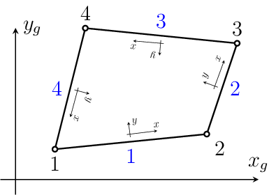
Fig. 5 PlaneStress2d element. Node numbering, edge numbering and definition of local edge c.s.(a).
Keyword |
planestress2d |
Description |
2D quadrilateral element for plane stress analysis |
Specific parameters |
[ |
Parameters |
|
Unknowns |
Two dofs (u-displacement, v-displacement) are required in each node. |
Approximation |
Linear approximation of displacements and geometry. |
Integration |
Integration of membrane strain terms using Gauss integration formula in 1, 4 (default), 9 or
16 integration points. The default number of integration points used can be overloaded using
|
Features |
Nonlocal constitutive support, Geometric nonlinearity support. |
CS properties |
cross section thickness is required. |
Loads |
Body loads are supported. Boundary loads are supported and computed using numerical integration. The side numbering is following. Each i-th element side begins in i-th element node and ends on next element node (i+1-th node or 1-st node, in the case of side number 4). The local positive edge x-axis coincides with side direction, the positive local edge y-axis is rotated 90 degrees anti-clockwise (see fig. (PlaneStress2d element. Node numbering, edge numbering and definition of local edge c.s.(a).)). |
Nlgeo |
0, 1. |
Status |
Reliable |
Tests/Examples |
sm/idm08.in, sm/idm11.in, sm/materOrient01.in, sm/concrete_fcm_visco.in, sm/EC2creep_casting.in, sm/control_switch_1.in, sm/control_switch_2.in, sm/hangingnode01.in, sm/hangingnode02.in, sm/hangingnode03.in (and 23 more) |
Keyword |
linquad3dplanestress |
Description |
3D quadrilateral element for plane stress analysis |
Specific parameters |
[ |
Parameters |
|
Unknowns |
Three dofs (u-displacement, v-displacement, w-displacement) are required in each node. |
Approximation |
Linear approximation of displacements and geometry. |
Integration |
Integration of membrane strain terms using Gauss integration formula in 1, 4 (default), 9 or
16 integration points. The default number of integration points used can be overloaded using
|
Features |
Nonlocal constitutive support, Geometric nonlinearity support. |
CS properties |
cross section thickness is required. |
Loads |
Body loads are supported. Boundary loads are supported and computed using numerical integration. The side numbering is following. Each i-th element side begins in i-th element node and ends on next element node (i+1-th node or 1-st node, in the case of side number 4). The local positive edge x-axis coincides with side direction, the positive local edge y-axis is rotated 90 degrees anti-clockwise (see fig. (PlaneStress2d element. Node numbering, edge numbering and definition of local edge c.s.(a).)). |
Nlgeo |
0, 1. |
Status |
Basic functionality tested, element loads need further testing. |
Tests/Examples |
QPlaneStress2d
Implementation of quadratic isoparametric eight-node quadrilateral plane-stress finite element. Each node has 2 degrees of freedom. The node numbering is anti-clockwise and is explained in fig. (QPlaneStress2d element - node numbering.). The element features are summarized in Table 8.
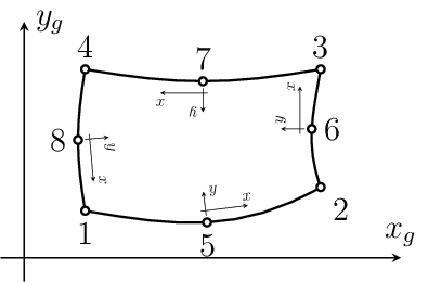
Fig. 6 QPlaneStress2d element - node numbering.
Keyword |
qplanestress2d |
Description |
2D quadratic isoparametric plane stress element |
Specific parameters |
[ |
Parameters |
|
Unknowns |
Two dofs (u-displacement, v-displacement) are required in each node. |
Approximation |
Quadratic approximation of displacements and geometry. |
Integration |
Full integration using Gauss integration formula in 4 (the default), 9 or 16 integration
points. The default number of integration points used can be overloaded using |
Features |
Adaptivity support. |
CS properties |
Cross section thickness is required. |
Loads |
Body and boundary loads are supported. |
Nlgeo |
0, 1. |
Status |
Stable |
Tests/Examples |
TrPlaneStress2d
Implements an triangular three-node constant strain plane-stress finite element. Each node has 2 degrees of freedom. The node numbering is anti-clockwise. The element features are summarized in Table 9.
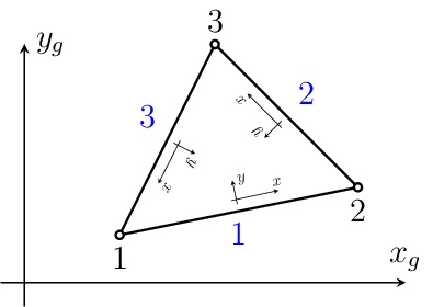
Fig. 7 TrPlaneStress2d element - node and side numbering.
Keyword |
trplanestress2d |
Description |
2D linear triangular isoparametric plane stress element |
Unknowns |
Two dofs (u-displacement, v-displacement) are required in each node. |
Approximation |
Linear approximation of displacements and geometry. |
Integration |
Integration of membrane strain terms using one point gauss integration formula. |
Features |
Nonlocal constitutive support, Edge load support, Geometric nonlinearity support, Adaptivity support. |
CS properties |
Cross section thickness is required. |
Loads |
Body loads are supported. Boundary loads are supported and are computed using numerical integration. The side numbering is following. Each i-th element side begins in i-th element node and ends on next element node (i+1-th node or 1-st node, in the case of side number 3). The local positive edge x-axis coincides with side direction, the positive local edge y-axis is rotated 90 degrees anti-clockwise (see fig. (TrPlaneStress2d element - node and side numbering.)). |
Nlgeo |
0, 1. |
Status |
Reliable |
Tests/Examples |
sm/deadweight03.in, sm/adapt01.in, sm/patch104.in, sm/setprops01.in, sm/patch130.in, sm/patch102.in, sm/distancebasedaveraging.in, sm/stressbasedaveraging.in, sm/layeredcs01.in |
QTrPlStr
Implementation of quadratic six-node plane-stress finite element. Each node has 2 degrees of freedom. Node numbering is anti-clockwise and is shown in fig. (QTrPlStr element - node and side numbering.). The element features are summarized in Table Table 10.
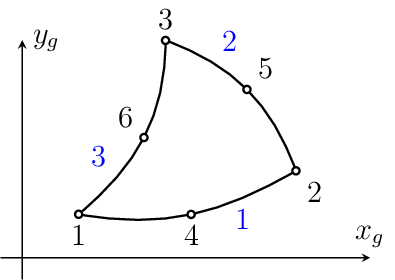
Fig. 8 QTrPlStr element - node and side numbering.
Keyword |
qtrplstr |
Description |
2D quadratic triangular plane stress element |
Specific parameters |
[ |
Parameters |
|
Unknowns |
Two dofs (u-displacement, v-displacement) are required in each node. |
Approximation |
Quadratic approximation of displacements and geometry. |
Integration |
Full integration using gauss integration formula in 4 points (the default) or in 7 points
(using |
Features |
Adaptivity support (error indicator). |
CS properties |
Cross section thickness is required. |
Loads |
Boundary loads are supported. |
Nlgeo |
0, 1. |
Status |
|
Tests/Examples |
sm/patch140.in (and 1 more) |
TrPlaneStrRot
Implementation of triangular three-node plane-stress finite element with independent rotation field. Each node has 3 degrees of freedom. The element features are summarized in Table 11.
The generalization of this element, that can be positioned arbitrarily in space is
trplanestrrot3d element. This element requires 6 degrees of freedon in each
node. The element features are summarized in Table 12.
The implementation is based on the following paper: Ibrahimbegovic, A., Taylor, R.L., Wilson, E. L.: A robust membrane qudritelar element with rotational degrees of freedom, Int. J. Num. Meth. Engng., 30, 445-457, 1990. The rotation field is defined as \(\omega = \del{1}{2}(\der{v}{x}-\der{u}{y}) = \nabla_u\mbf{u}\). The following form of potential energy functial is assumed:
where \(\mbf{\tau}\) is pseudo-stress (component of anti-symmetric stress tensor) working on dislocation \((\nabla_u\mbf{u}-\omega)\); the following constitutive relation foris assumed: \(\mbf{\tau} = G(\nabla_u\mbf{u}-\omega)\), where \(G\) is elasticity modulus in shear.
Keyword |
trplanestrrot |
Description |
2D linear triangular plane stress element with rotational DOFs |
Specific parameters |
[ |
Parameters |
|
Unknowns |
Three dofs (u-displacement, v-displacement, z-rotation) are required in each node. |
Approximation |
Linear approximation of displacements and geometry. |
Integration |
Integration of membrane strain terms using gauss integration formula in 4 points (default)
or using 1 or 7 points (using |
Features |
|
CS properties |
Cross section thickness is required. |
Loads |
|
Nlgeo |
|
Status |
|
Tests/Examples |
Keyword |
trplanestrrot3d |
Description |
3D linear triangular plane stress element with rotational DOFs |
Specific parameters |
[ |
Parameters |
|
Unknowns |
Six dofs (u-displacement, v-displacement, w-displacement, x-rotation, y-rotation, z-rotation) are required in each node. |
Approximation |
Linear approximation of displacements and geometry. |
Integration |
Integration of membrane strain terms using gauss integration formula in 4 points (default)
or using 1 or 7 points (using |
Features |
|
CS properties |
Cross section thickness is required. |
Loads |
|
Nlgeo |
|
Status |
TrPlaneStressRotAllman
Implementation of triangular three-node plane-stress with nodal rotations. Each node has 3 degrees of freedom. The element features are summarized in Table Table 13.
The generalization of this element, that can be positioned arbitrarily in space is
trplanestressrotallman3d element. This element requires 6 degrees of freedon in
each node. The element features are summarized in Table
Table 14.
The implementation is based on the following paper: Allman, D.J.: A compatible triangular element including vertex rotations for plane elasticity analysis, Computers & Structures, vol. 19, no. 1-2, pp. 1-8, 1984. The element is based on plane stress element with quadratic interpolation. The displacements in midside nodes are expressed using vertex displacements and vertex rotations (for edge normal displacement component); the tangential component is interpolated from vertex values. For particular element side starting at i-th vertex and ending in j-th vertex the normal and tangential displacements at edge midpoint can be expressed as
where \(l\) is edge length. This allows to express global displacements in element midside nodes using vertex displacements and rotations. For a single edge, one obtains:
Keyword |
trplanestressrotallman |
Description |
2D linear triangular plane stress element with rotational DOFs |
Unknowns |
Three dofs (u-displacement, v-displacement, z-rotation) are required in each node. |
Approximation |
Linear approximation of geometry, quadratic interpolation of displacements. |
Integration |
Integration of membrane strain terms using gauss integration formula in 4 points. |
Zero energy mode |
The zero energy mode (equal rotations) is handled by adding additional energy term preventing spurious modes. |
Features |
|
CS properties |
Cross section thickness is required. |
Loads |
|
Nlgeo |
|
Status |
|
Tests/Examples |
Keyword |
trplanestressrotallman3d |
Description |
2D linear triangular plane stress element with rotational DOFs |
Unknowns |
Six dofs (D_u, D_v, D_w, R_x, R_y, R_z) are required in each node. |
Approximation |
Linear approximation of geometry, quadratic interpolation of displacements. |
Integration |
Integration of membrane strain terms using gauss integration formula in 4 points. |
Zero energy mode |
The zero energy mode (equal rotations) is handled by adding additional energy term preventing spurious modes. |
Features |
|
CS properties |
Cross section thickness is required. |
Loads |
|
Nlgeo |
|
Status |